


Return to Section TOC Return to Section TOC Return to Section TOC Return to Section TOC
Return to Master TOC Return to Master TOC Return to Master TOC Return to Master TOC
TROUBLESHOOTING & REPAIR
F-22 F-22
POWER MIG 300
OUTPUT RECTIFIER ASSEMBLY TEST (continued)
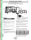
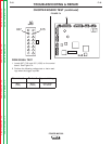
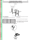
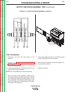
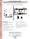
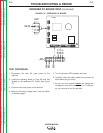
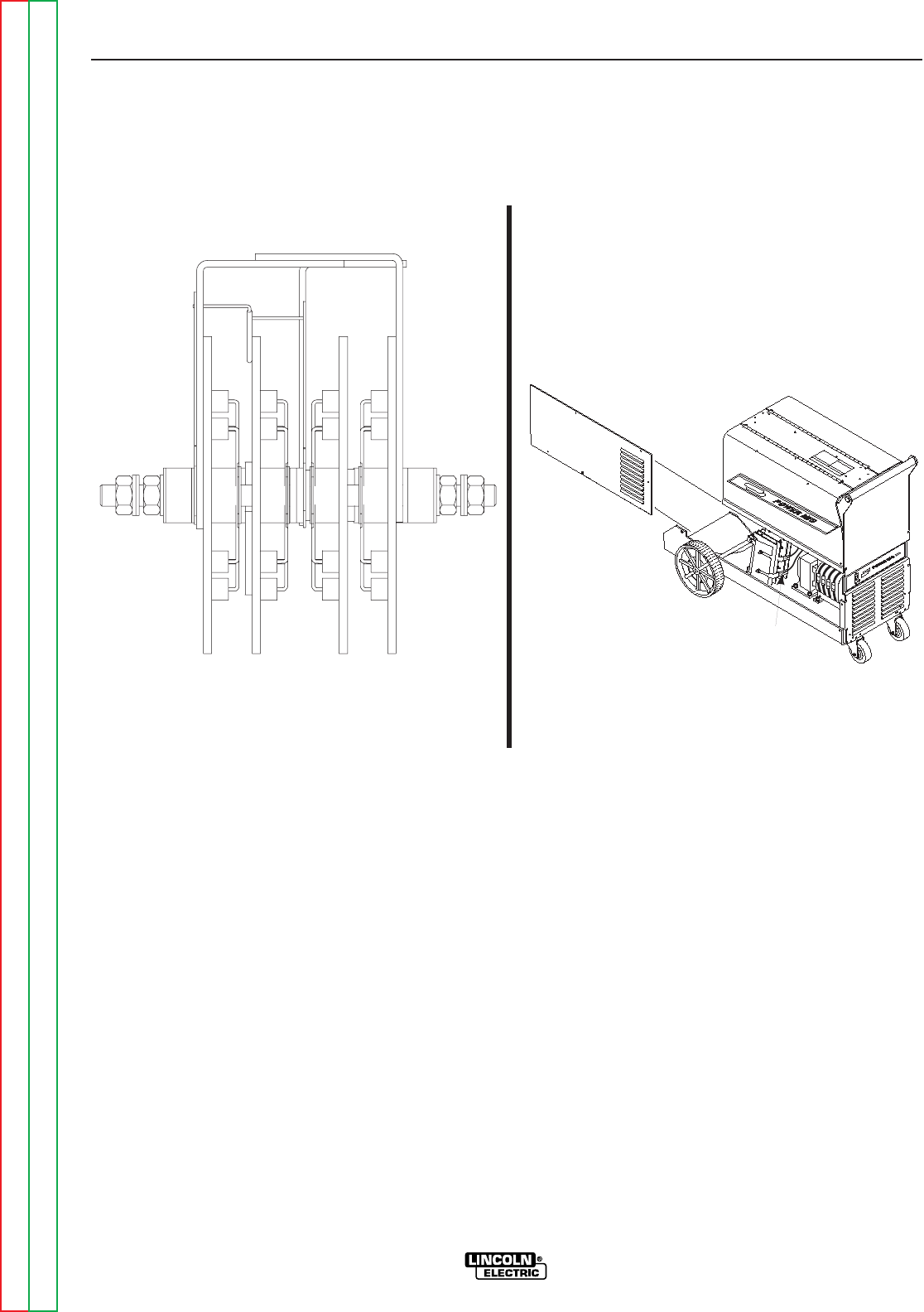
FIGURE F.7– OUTPUT RECTIFIER ASSEMBLY LOCATION
TEST PROCEDURE
1. Disconnect the main AC input power to the
machine.
2. Perform the Chopper Assembly Capacitor
Discharge procedure.
3. Locate and disconnect the negative lead from the
output rectifier bridge assembly.
NOTE: Do not disassemble the rectifier assembly.
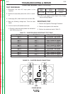
4. Test for shorted or leaky diodes by checking from
the outside plate (A) to inside plate (A) then reverse
your leads and recheck the same plates. Do the
same to plate B. The readings should be high resis-
tance in one polarity and low resistance in the oppo-
site polarity. See Figure F.7.
5. If any of the diodes are leaky or shorted the output
rectifier assembly should be replaced.
6. When the test is complete, replace the negative out-
put previously removed.
7. Replace case side.
A A B B
Front
-
+
Negative Lead
300