


TROUBLESHOOTING & REPAIR
F-41 F-41
POWER MIG 300
Return to Section TOC Return to Section TOC Return to Section TOC Return to Section TOC
Return to Master TOC Return to Master TOC Return to Master TOC Return to Master TOC
OUTPUT RECTIFIER
REMOVAL AND REPLACEMENT (continued)
ELECTRIC SHOCK can kill.
High voltage is present when input power is applied to
the machine.
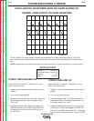
NOTE: Cut cable ties as needed to improve access.
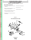
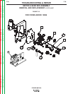
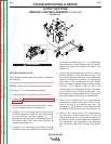
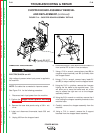
See Figure F.13 for the following procedure.
1. Disconnect main input power from the machine.
2. Perform the Chopper Board Capacitor Discharge
Procedure.
3. Remove the right side panel using a 3/8 in. nutdriv-
er. (as viewed from the front of machine).
4. Using the 1/2 in. wrenches, remove heavy lead B1
and small resistor lead 2530 from the output rectifi-
er lower terminal, marked negative (-) . For
reassembly, note placement of the fasteners: bolt,
flat washer, heavy lead, small lead, terminal, flat
washer, lock washer, nut.
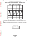
5. Using the 1/2 in. wrenches, remove heavy lead B5
and small resistor lead 2520 from the output rectifi-
er terminal marked positive (+) . For reassembly,
note placement of the fasteners: bolt, flat washer,
heavy lead, small lead, terminal, flat washer, lock
washer, nut.
6. Using a slot head screwdriver and a 3/8 in. wrench,
remove Resistor R1 from the machine base. This
will provide additional clearance for accessing fas-
teners and removing the rectifier. For reassembly,
note order of the components for the resistor:
screw, star washer, plastic insulator, resistor, plastic
insulator. This assembly rests on top of the
machine base. From beneath the base a flat wash-
er, lock washer, and nut attach to the screw. It is a
good practice to loosely assemble the parts and set
the resistor aside until ready to be reassembled.
7. Using a 1/2 in. wrench and a 1/2 in. socket wrench
with extension, remove heavy lead X2 from the ter-
minal at the top of the rectifier, near side. For
reassembly, note placement of the fasteners: bolt,
flat washer, heavy lead, terminal, lock washer, nut.
8. Using a 1/2 in. wrench and a 1/2 in. socket wrench
with extension, remove heavy lead X1 (from the
output choke) from the other terminal at the top of
the rectifier, nearer to the chopper board assembly.
For reassembly, note placement of the fasteners:
bolt, flat washer, heavy lead, terminal, lock washer,
nut.
FIGURE F.13
11
7
9
8
5
4
6
WARNING