


TROUBLESHOOTING & REPAIR
F-20 F-20
POWER MIG 300
Return to Section TOC Return to Section TOC Return to Section TOC Return to Section TOC
Return to Master TOC Return to Master TOC Return to Master TOC Return to Master TOC
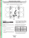
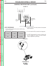
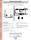
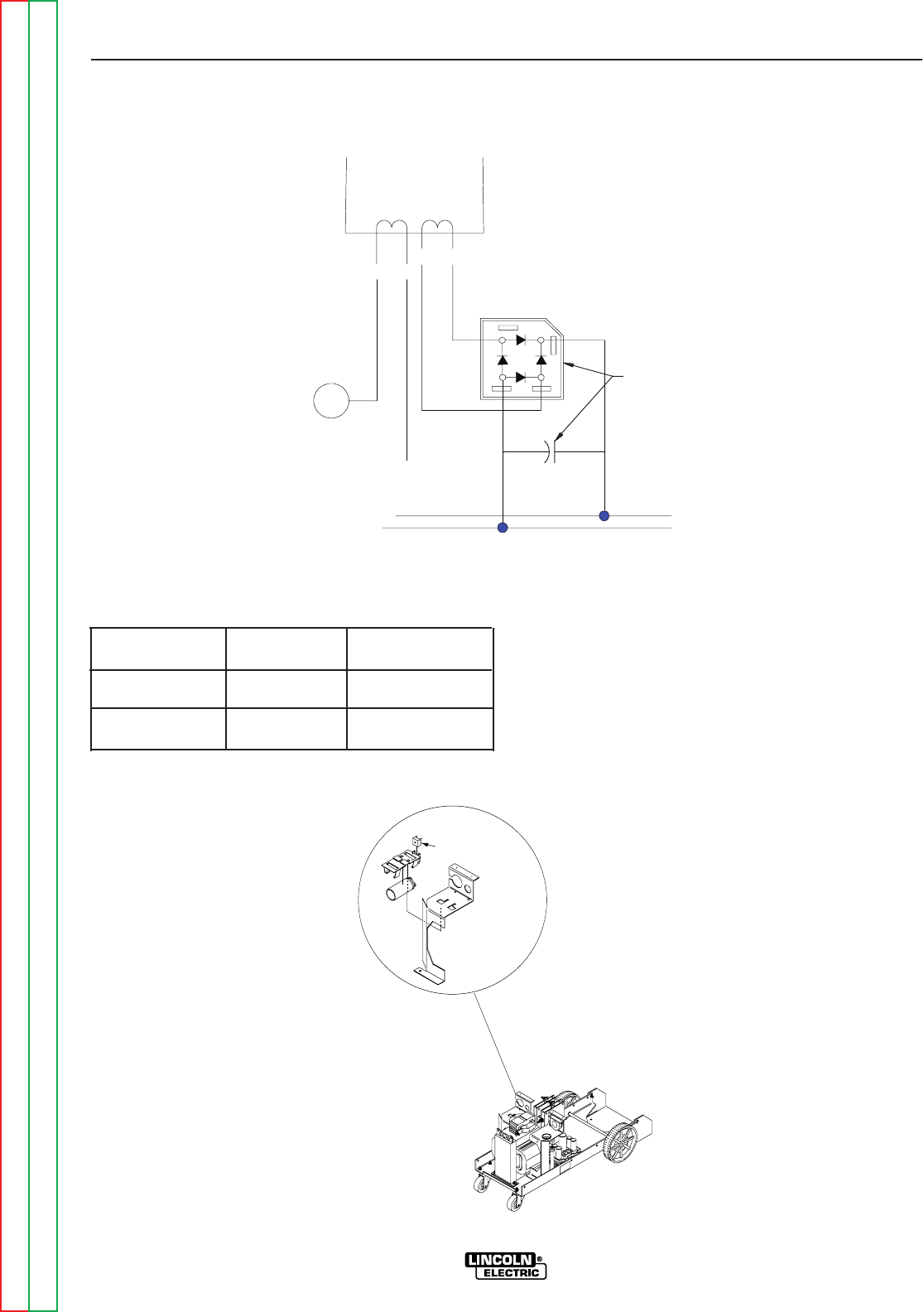
CONTROL RECTIFIER TEST (continued)
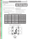
FIGURE F.5
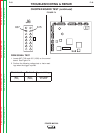
FIGURE F.6
-
+
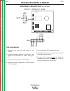
CONTROL RECTIFIER
+
6800/75
X6X5
X4X3
30 VAC115 VAC
FAN
LOCATED ON
TRANSFORMER
BAFFLE
+ 42VDC
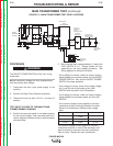
TEST PROCEDURE
1. Find the following leads at the control rectifier using
figures F.5 and F.6.
2. Carefully connect the meter probes to the exposed
lead connections.
3. Turn the machine ON to conduct the voltage test.
4. If the DC voltage tested is incorrect or missing, and
the AC voltages are correct, the control rectifier
bridge or capacitor may be faulty.
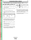
From Lead
471B
To Lead
Expected Voltage
472B 42 VDC
X5
X6 30 VAC
CONTROL RECTIFIER