


TROUBLESHOOTING & REPAIR
F-30 F-30
POWER MIG 300
Return to Section TOC Return to Section TOC Return to Section TOC Return to Section TOC
Return to Master TOC Return to Master TOC Return to Master TOC Return to Master TOC
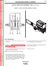
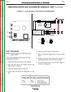
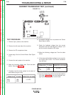
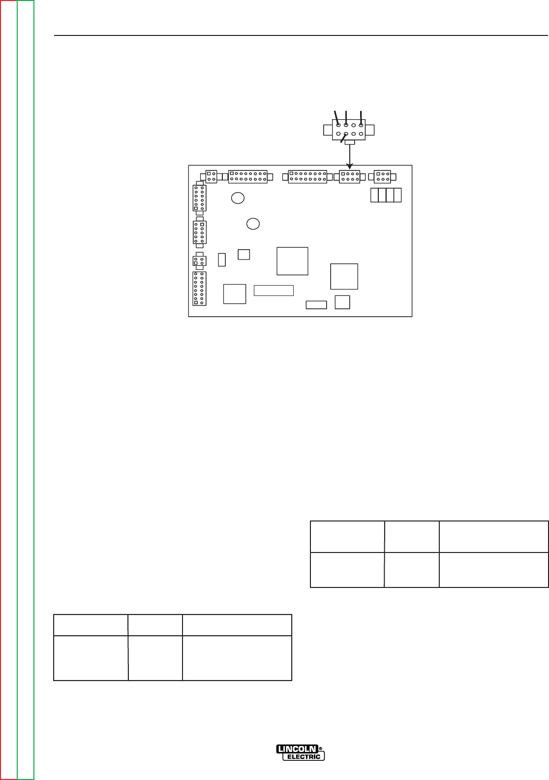
CURRENT TRANSDUCER TEST (continued)
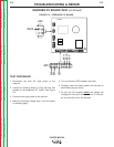
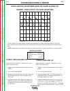
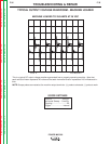
FIGURE F.10
L11088-1
J8
804
802
801
806
TEST PROCEDURE
1. Remove input power to the machine
2. Remove the left case side of the machine.
3. Remove the PC compartment door.
4. Locate plug J8 at the Control Board. See Figure
F.10.
5. Connect the main power to the machine.
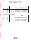
6. Make the following voltage test. From the table
below. Also see Table F.2.
7. Carefully insert the meter probes into the back of
each Molex plug pin cavity.
8. If excepted voltages are not present the Control
Board may be faulty.
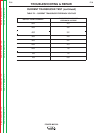
9. Check the feedback voltage from the current
transducer with the Power Mig set on Mode 1 or 2
and the machine loaded to 250 amps.
10. Make the following voltage test. From the table
below.
11. If the measured feedback voltage is not correct for
the output load current. The current transducer
may be faulty.
12. If for any reason the machine cannot be loaded to
250 amps, Table F.2 shows what feedback volt-
age is produced at various current loads.
FROM LEAD TO LEAD EXPECTED VOLTAGE
802+ 806- +15 VDC
(2J8) (6J8)
FROM LEAD TO LEAD EXPECTED VOLTAGE
801 806 2.0 VDC
(1J8) (6J8)