


Return to Section TOC Return to Section TOC Return to Section TOC Return to Section TOC
Return to Master TOC Return to Master TOC Return to Master TOC Return to Master TOC
TROUBLESHOOTING & REPAIR
F-25 F-25
POWER MIG 300
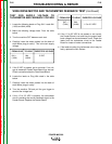
WIRE DRIVE MOTOR AND TACHOMETER FEEDBACK TEST (continued)
TEST FOR SUPPLY VOLTAGE TO
TACHOMETER AND FEEDBACK VOLTAGE
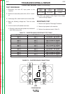
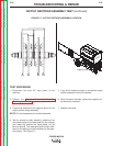
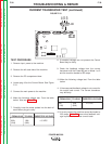
1. Locate the following leads on Plug J84. Leads 841
(1J84) and 844 (4J84)
2. Make the following voltage tests. From the table
below.
3. Turn the machine OFF between each test.
4. Carefully insert the meter probes into the back of
each Molex plug pin cavity. This is the tach supply
voltage.
5. If the 5 VDC is present, go to next step. If no volt-
age is measured Feeder Head Board may be bad.
Check connections back to Feed Head Board.
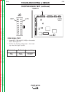
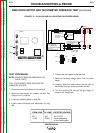
6. Locate the leads on Plug J84 noted in the table
below.
7. Carefully insert the meter probes into the back of
each Molex plug pin cavity
8. Turn the machine ON and pull the gun trigger to
conduct the voltage test.
9. If the 1.5 to 3.5 VDC is present, the tachometer
circuit is sending the correct feedback signal to the
Feeder Board. Replace the Feeder Board.
10. If the 1.5 to 3.5 VDC is not present or not correct,
the Feeder Board is not receiving the proper feed-
back voltage from the tachometer circuit. Check the
leads from the tachometer circuit to the Feeder
Board for loose or broken connections.
11. If the leads are okay, the tachometer circuit may be
faulty, replace the tach Sensor.
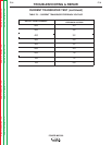
FROM LEAD TO LEAD EXPECTED VOLTAGE
847 + 844 -
1.5 to 3.5 VDC
(7J84) (4J84)
FROM LEAD TO LEAD EXPECTED VOLTAGE
841 + 844 - 5 VDC
(1J84) (4J84)