


POWER MIG 300
Return to Section TOC Return to Section TOC Return to Section TOC Return to Section TOC
Return to Master TOC Return to Master TOC Return to Master TOC Return to Master TOC
INSTALLATION
A-6
A-6
DO NOT ATTACH THE REGULATOR IF OIL,
GREASE OR DAMAGE IS PRESENT! Inform your
gas supplier of this condition. Oil or grease in the
presence of high pressure oxygen is explosive.
3. Stand to one side away from the outlet and open
the cylinder valve for an instant. This blows away
any dust or dirt which may have accumulated in the
valve outlet.
Be sure to keep your face away from the valve
outlet when “cracking” the valve.
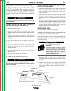
4. Attach the flow regulator to the cylinder valve and
tighten the union nut(s) securely with a wrench.
NOTE: If connecting to 100% CO
2
cylinder, insert
regulator adapter between regulator and cylinder
valve. If adapter is equipped with a plastic washer,
be sure it is seated for connection to the CO
2
cylin-
der.
5. Attach one end of the inlet gas hose to the outlet
fitting of the flow regulator, the other end to the
POWER MIG 300 rear fitting, and tighten the union
nuts securely with a wrench.
6. Before opening the cylinder valve, turn the regula-
tor adjusting knob counterclockwise until the
adjusting spring pressure is released.
7. Standing to one side, open the cylinder valve slow-
ly a fraction of a turn. When the cylinder pressure
gauge pointer stops moving, open the valve fully.
Never stand directly in front of or behind the flow
regulator when opening the cylinder valve. Always
stand to one side.
------------------------------------------------------------------------
8. The flow regulator is adjustable. Adjust it to the flow
rate recommended for the procedure and process
being used before making the weld.
WARNING
WARNING