


INSTALLATION
A-7 A-7
POWERARC® 5500
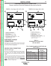
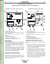
Cable Installation
Install the welding cables to your POWERARC® 5500
as follows. See Figure A.1 for the location of parts.
1. The gasoline engine must be OFF to install weld-
ing cables.
2. Remove the 1/2 - 13 flanged nuts from the output
terminals.
3. Connect the electrode holder and work cables to
the weld output terminals. You can connect either
cable to either terminal, since the POWERARC®
5500 provides AC weld current.
4. Tighten the flanged nuts securely.
5. Be certain that the metal piece you are welding
(the “work”) is securely connected to the work
clamp and cable.
6. Check and tighten the connections periodically.
• Loose connections will cause the output termi-
nals to overheat. The terminals may eventually
melt.
• Do not cross the welding cables at the output
terminal connection. Keep the cables isolated
and separate from one another.
Lincoln Electric offers a welding accessory kit with the
properly specified welding cables. See the ACCES-
SORIES section of this manual for more information.
MACHINE GROUNDING
Because the POWERARC® 5500 creates
its own power from its gasoline-engine
driven generator, you do not need to
connect the machine frame to an earth
ground. However, for best protection against electrical
shock, connect a heavy gauge wire from the ground
stud located on the bottom center of the output panel
(see Figure A.1) to a suitable earth ground such as a
metal pipe driven into the ground.
Do not ground the machine to a pipe that carries
explosive or combustible material.
When the POWERARC® 5500 is mounted on a truck
or a trailer, the machine generator ground
stud MUST be securely connected to the
metal frame of the vehicle. See Figure
A.1. The ground stud is marked with the
symbol.
PLUGS AND HAND-HELD EQUIPMENT
For further protection against electric shock, any elec-
trical equipment connected to the generator recepta-
cles must use a three-blade, grounded type plug or an
Underwriter’s Laboratories (UL) approved double insu-
lation system with a two-blade plug.
Ground fault protection is needed for hand held equip-
ment.
Never operate this machine with damaged or
defective cords. All electrical equipment must be
in safe condition.
-------------------------------------------------------------
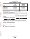
AUXILIARY POWER RECEPTACLES
The control panel of the POWERARC® 5500 features
two auxiliary power receptacles:
• A 20 amp, 120 volt duplex (double outlet) recepta-
cle
• A 20 amp 240 volt simplex (single outlet) receptacle.
See Figure A.1.
Through these receptacles the machine can supply up
to 4,000 rated continuous watts and 5,500 surge watts
of single-phase AC power.
CAUTION
WARNING
WARNING
Return to Section TOC Return to Section TOC Return to Section TOC Return to Section TOC
Return to Master TOC Return to Master TOC Return to Master TOC Return to Master TOC