


ENGINE THROTTLE ADJUSTMENT TEST
ROBIN/SUBARU ENGINE (continued)
TROUBLESHOOTING AND REPAIR
F-20 F-20
POWERARC® 5500
TEST PROCEDURE
This test can be conducted by any of
three methods.
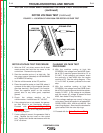
Strobe-tach Method:
1. Stop the engine and remove the
spark plug wire to prevent accidental
kickback or starting.
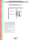
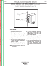
2. With the black or red marking pencil,
place a mark on one of the blower
paddles, which can be reached
through the vent slots in the end
bracket. See Figure F.4.
3. Connect the strobe-tach according
the manufacturer’s instructions.
4. Reconnect the spark plug wire and
start the engine. Direct the strobe-
tach light on the blower paddle and
synchronize it to the rotating mark.
The tach should read 3700 RPM.
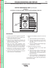
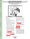
5. Using the 10mm socket wrench,
slightly loosen the throttle locking
nut. See Figure F.5.
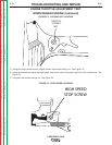
5. Using the screwdriver adjust the
high speed stop screw until the tach
reads 3700 RPM. See Figure F.6.
5. Re-tighten the throttle locking nut.
See Figure F.5.
Frequency Counter Method:
1. Plug the frequency counter into one
of the 115 VAC auxiliary receptacles.
2. Start the engine and check the
frequency counter. At the proper
RPM (3700), the counter should read
62 Hz.
3. Using the 10mm socket wrench,
slightly loosen the throttle locking
nut. See Figure F.5.
4. Using the screwdriver, adjust the
high speed stop screw until the fre-
quency counter reads 3700 RPM.
See Figure F.6.
5. Re-tighten the throttle locking nut.
See Figure F.5.
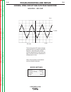
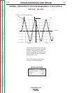
Oscilloscope Method:
1. Connect the oscilloscope according
to the manufacturer’s instructions.
At 3700 RPM, the waveform should
exhibit a period of 16.2 milliseconds.
Refer to the NORMAL OPEN
CIRCUIT VOLTAGE WAVEFORM
(115 VAC SUPPLY) HIGH IDLE - NO
LOAD in this section of the manual.
MARK
FIGURE F.4 - MARK LOCATION
Return to Section TOC Return to Section TOC Return to Section TOC Return to Section TOC
Return to Master TOC Return to Master TOC Return to Master TOC Return to Master TOC