


STATOR/ROTOR
REMOVAL AND REPLACEMENT PROCEDURE (continued)
TROUBLESHOOTING AND REPAIR
F-37 F-37
POWERARC® 5500
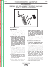
14. Slide a short length of 2 X 4 under
the engine to support it when the
stator is removed.
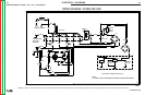
15. With the 1/2” wrench, remove the 2
nuts that hold the stator end brack-
et support. See Figure F.12 for
location. There are 2 split-ring lock
washers along with the nuts.
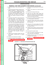
16. With the 7/16” socket and 7/16”
end wrench, remove the 4 thru-
bolts for the generator assembly.
See Figure F.12. All 4 bolts have a
split-ring lock washer under the
head and a shake-proof star wash-
er on the nut side. The bolts must
point toward the engine for
reassembly.
17. Lift up the stator and slide out the
support bracket. The engine will
now rest on the 2 X 4.
18. With the babbitt/leather/wooden
mallet, tap off the end bracket.
Alternate sides as you tap; watch
the bearing to judge the amount of
movement you’re getting.
19. Once the end bracket is off, care-
fully pull off the stator. IMPROPER
HANDLING OF THE STATOR CAN
RESULT IN SHORTED WINDINGS
AND/OR LOST OUTPUT.
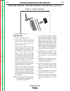
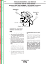
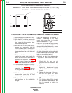
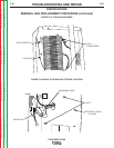
THRU-
BOLTS
THRU-
BOLTS
NUTS
SUPPORT
FIGURE F.12 – STATOR END BRACKET SUPPORT AND THRU-BOLTS
Return to Section TOC Return to Section TOC Return to Section TOC Return to Section TOC
Return to Master TOC Return to Master TOC Return to Master TOC Return to Master TOC