


OPERATION
B-3 B-3
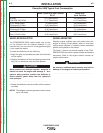
POWERARC® 5500
LIMITATIONS
• The POWERARC® 5500 is not recommended for
any processes besides those that are normally per-
formed using stick welding (SMAW) procedures.
• The POWERARC® 5500 is not recommended for
pipe thawing.
• During welding, generator power is limited to 100
watts, and output voltages can drop from 120 to 80
volts and 240 to 160 volts. Therefore, DO NOT
OPERATE ANY SENSITIVE ELECTRICAL EQUIP-
MENT WHILE YOU ARE WELDING.
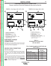
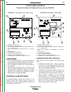
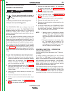
CONTROLS AND SETTINGS
All generator/welder controls are located on the
Output Control Panel. Gasoline engine controls are
mounted on the engine. See Figures B.1 and B.2 and
the explanations that follow.
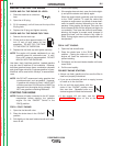
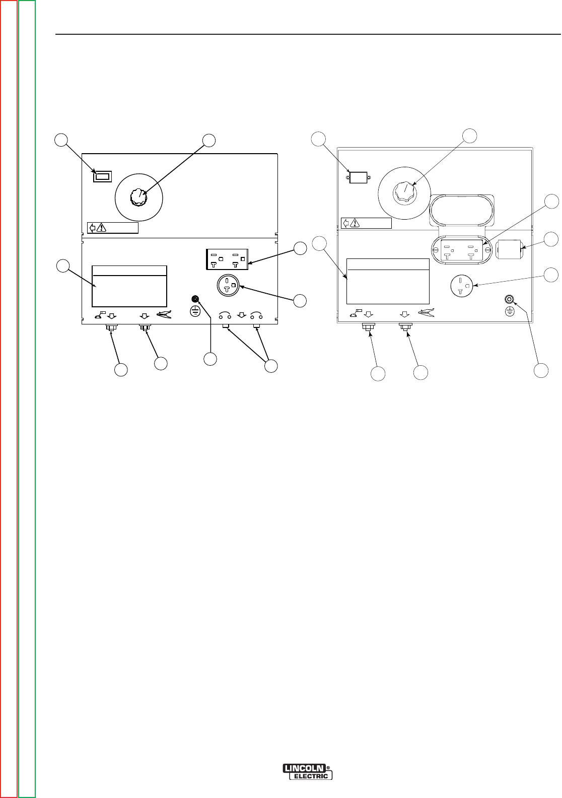
GENERATOR/WELDER CONTROLS
See Figure B.1 for the location of the following fea-
tures:
1. CURRENT CONTROL DIAL: Adjusts continuous
current output. The amperages on the dial corre-
spond to the average amperages needed for spe-
cific Lincoln welding electrodes.
2. ELECTRODE SELECTION GUIDE: Provides rec-
ommended electrode type, size, and welder out-
put setting based on the thickness of the work.
3. WELD OUTPUT TERMINAL (TO ELECTRODE
HOLDER) WITH 1/2 - 13 FLANGE NUT: Pro vides
the connection point for either the electrode hold-
er or the work cable. (Because the POWERARC®
5500 is an AC output machine, either output ter-
minal can be used for either cable.)
POWER ARC POWER ARC 55550000
ELECTRODE SELECTION GUIDEELECTRODE SELECTION GUIDE
8080
9090
100100
7
070
AMPSAMPS
AMPSAMPS
AMPSAMPS
AMPSAMPS
WARNINGWARNING
AMPSAMPS
125125
GENERATORGENERATOR
8
7
6
5
3
1
2
4
9
8080
9
090
100100
7070
AMPSAMPS
AMPSAMPS
AMPSAMPS
AMPSAMPS
WARNINGWARNING
AMPSAMPS
125125
GENERATORGENERATOR
E
LECTRODE SELECTION GUIDEELECTRODE SELECTION GUIDE
7
6
8
3
5
1
4
POWER ARC 5500POWER ARC 5500
2
9
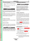
OUTPUT PANEL CONTROLS
Physical Location of Components may vary by Code No.
1. CURRENT CONTROL DIAL
2. ELECTRODE SELECTION GUIDE
3. WELD OUTPUT TERMINAL (TO ELECTRODE HOLDER) WITH
1/2 - 13 FLANGE NUT
4. WELD OUTPUT TERMINAL (TO WORK) WITH 1/2 - 13 FLANGE
NUT
5. GROUND STUD
6. 20 AMP CIRCUIT BREAKERS (2)
7. 20 AMP, 240 VOLT RECEPTACLE
8. 20 AMP, 120 VOLT DUPLEX RECEPTACLE
9. TACHOMETER / HOUR METER (CODE 11215 ONLY)
1. CURRENT CONTROL DIAL
2. ELECTRODE SELECTION GUIDE
3. WELD OUTPUT TERMINAL (TO ELECTRODE HOLDER) WITH
1/2 - 13 FLANGE NUT
4. WELD OUTPUT TERMINAL (TO WORK) WITH 1/2 - 13 FLANGE
NUT
5. GROUND STUD
6. 20 AMP CIRCUIT BREAKER
7. 20 AMP, 240 VOLT RECEPTACLE
8. 20 AMP, 120 VOLT DUPLEX RECEPTACLE
9. TACHOMETER / HOUR METER (CODE 11404 ONLY)
FIGURE B.1 (For Codes 11182, 11187, 11215)
FIGURE B.2 (For Codes 11403, 11404)
Return to Section TOC Return to Section TOC Return to Section TOC Return to Section TOC
Return to Master TOC Return to Master TOC Return to Master TOC Return to Master TOC