


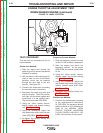
ROTOR VOLTAGE AND FLASHING VOLTAGE TEST PROCEDURE
(continued)
TROUBLESHOOTING AND REPAIR
F-14 F-14
POWERARC® 5500
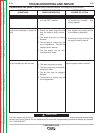
ROTOR VOLTAGE TEST PROCEDURE
1. With the 5/16” nut driver, remove the 8 sheet
metal screws that hold the top cover to the
control box. Remove the top cover.
2. Start the machine and run it at high idle. Set
the output control (rheostat) at the MAXIMUM
or GENERATOR setting.
3. Set the volt/ohmmeter at the DC position.
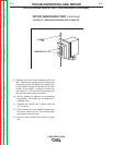
4. Place the positive probe on lead 200 where it
connects at the back of the rheostat (the mid-
dle wiper terminal). See Figure F.1 for location.
Place the negative probe on the machine
ground stud or any other good, unpainted
ground.
5. Check the voltage reading on the
volt/ohmmeter. It should read 45 - 48 VDC.
6. If the voltage is low or not present, the genera-
tor field circuit is not functioning correctly.
Proceed with Flashing Voltage Test
Procedure. C1, R1, or D1 may also be faulty.
See wiring diagram.
7. If rotor voltage is correct, the generator field is
okay. Replace the top cover on the control
box. Tighten the 8 sheet metal screws with the
5/16” nut driver.
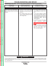
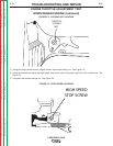
FLASHING VOLTAGE TEST
PROCEDURE
8. With the machine running at high idle
(3700RPM), the voltage from lead #205 (locat-
ed at D2) to machine ground should be 1.5 to
2.0 VAC. If this voltage is not present, check
the continuity of lead #205 from the engine
module to D2. See the wiring diagram. If the
1.5 to 2.0 VAC is present, proceed to the next
step.
9. With the machine running at high idle
(3700RPM), the voltage from lead 202B (locat-
ed at D2) to machine ground should be approx-
imately 1.6 VDC. If this voltage is not present
and the correct AC voltage is present at lead
#205, then diode D2 may be faulty.
10. If the voltage readings are correct in the two
prior steps, check the continuity of leads #202,
#202B, #202A, #201, #201A and #201B. See
the wiring diagram. Also check the brushes for
good contact with the rotor slip rings.
11. Proceed with the Rotor Resistance Test.
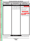
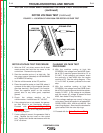
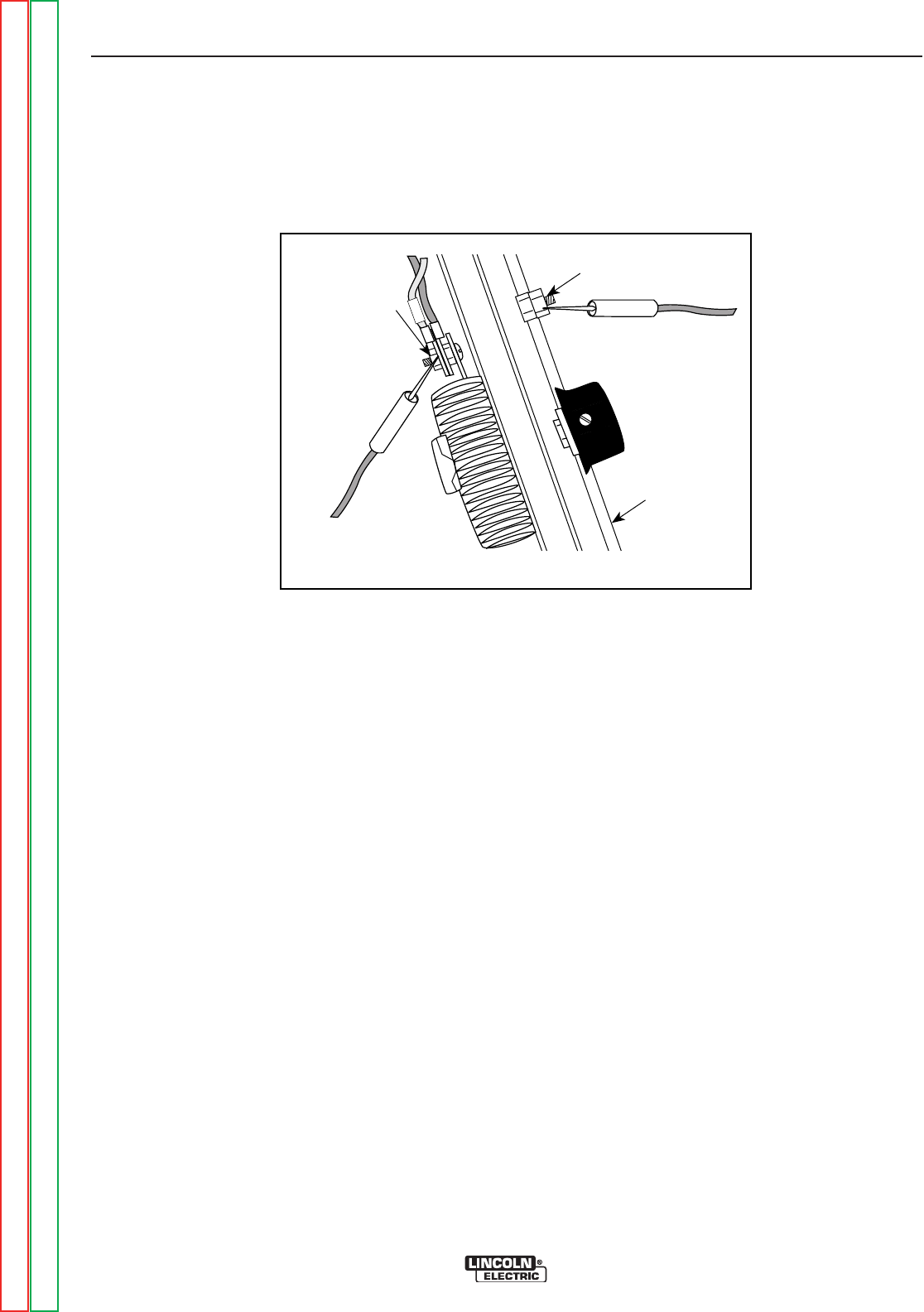
ROTOR VOLTAGE TEST (continued)
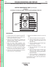
FIGURE F.1 - LOCATION OF LEAD 200A FOR ROTOR VOLTAGE TEST
200
LEAD 200
CONNECTION
GROUND STUD
OUTPUT PANEL
Return to Section TOC Return to Section TOC Return to Section TOC Return to Section TOC
Return to Master TOC Return to Master TOC Return to Master TOC Return to Master TOC