


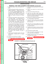
CAPACITOR AND/OR DIODE BRIDGE
REMOVAL AND REPLACEMENT PROCEDURE (continued)
TROUBLESHOOTING AND REPAIR
F-33 F-33
POWERARC® 5500
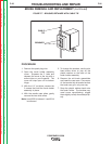
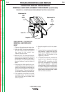
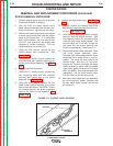
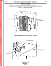
FIGURE F.10 - FIELD DIODE BRIDGE LOCATION
1. Remove the engine spark plug wire.
2. With the 5/16” nut driver, remove the
8 sheet metal screws that hold the
top cover to the control box.
Remove the top cover.
3. With the 5/16” nut driver and wrench,
remove the 6 screws that hold the
control panel in place (2 in the front, 2
in the back, 2 in the bottom). Move
the panel aside as far as the leads will
allow.
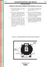
4. Discharge the field capacitor by con-
necting the jumper wire clips on the
black and the red wire terminals on
the top of the capacitor. See Figure
F.9 for location. Leave the clips on
for at least 5 seconds, then remove.
5. The field diode bridge (D1) is mount-
ed to the sheet metal just above the
capacitor. See Figure F.9. Remove
it using the phillips head screw dri-
ver.
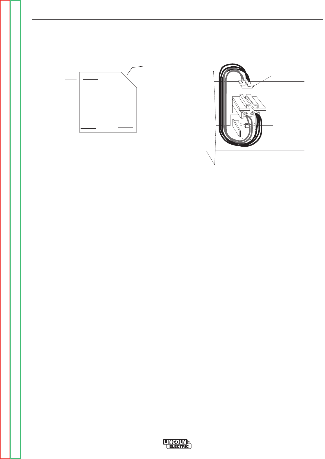
6. With the needle nose pliers, gently
remove the wires from the field
diode bridge. Note lead locations.
7. Replace the wires to their appropri-
ate locations on the new diode
bridge:
Lead 200 attached to the positive (+)
terminal. Depending on the bridge
used, this corner may be beveled
and/or marked with a + sign.
Lead 201 and 201B are piggy-backed
on the negative (–) terminal, which will
always be located diagonally across
from the positive (+) terminal.
Leads 9A and 7A are attached to the
AC side of the bridge and are attached
to the other two corner terminals. Either
lead can go on either terminal.
8. Mount the field diode bridge using
the screw. Use the slot head screw-
driver.
9. Check that the leads are not
grounded and for clearance and
tightness.
10. Replace the control panel and
tighten the sheet metal screws
with the 5/16” nut driver and 5/16”
wrench.
11. Replace the top cover of the con-
trol box and tighten the sheet
metal screws with the 5/16” nut dri-
ver.
12. The flashing diode (D2) is located
just above the field capacitor and
may be removed by cutting the
cable tie.
Feild Diode Bridge
7A
201
201B
9A
200
+
–
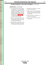
PROCEDURE - FIELD DIODE BRIDGE REMOVAL AND REPLACEMENT
Return to Section TOC Return to Section TOC Return to Section TOC Return to Section TOC
Return to Master TOC Return to Master TOC Return to Master TOC Return to Master TOC