


TROUBLESHOOTING AND REPAIR
F-36 F-36
POWERARC® 5500
STATOR/ROTOR
REMOVAL AND REPLACEMENT PROCEDURE (continued)
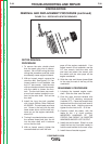
STATOR REMOVAL PROCEDURE
1. Remove engine spark plug wire to prevent
accidental kickback or starting.
2. With the 5/16” nut driver, remove the 8
sheet metal screws that hold the top cover
to the control box. Remove the top cover.
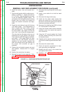
3. With the slot head screw driver, remove the
6 sheet metal screws that hold the control
panel to the control box - 2 on each side
and 2 on the bottom. You may need to use
the 5/16” end wrench on the engine side
because of limited clearance. Pull the
panel away from the control box.
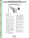
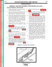
4. Using the 7/16” wrench, remove the two
bolted reactor lead connections. See
Figure F.15.
5. Using the 1/2” socket wrench, remove the
two bolts and star washers mounting the
reactor to the stator assembly. See Figure
F.15.
6. Carefully remove the reactor.
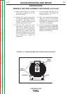
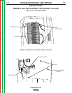
7. Using the 1/2” socket wrench, remove the
two remaining bolts and star washers
securing the control box to the stator
assembly. See Figure F.16.
8. Using the 5/16” wrench, remove the five
sheet metal screws securing the control
box to the stator frame. CAUTION: One of
the screws secures the green grounding
lead to the frame of the machine. See
Figure F.16.
9. Unplug the large molex plug. See Figure
F.16.
10. Carefully remove the flashing lead #205
from diode D2 and clear lead from the con-
trol box. See Figure F.15.
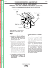
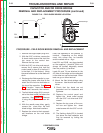
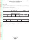
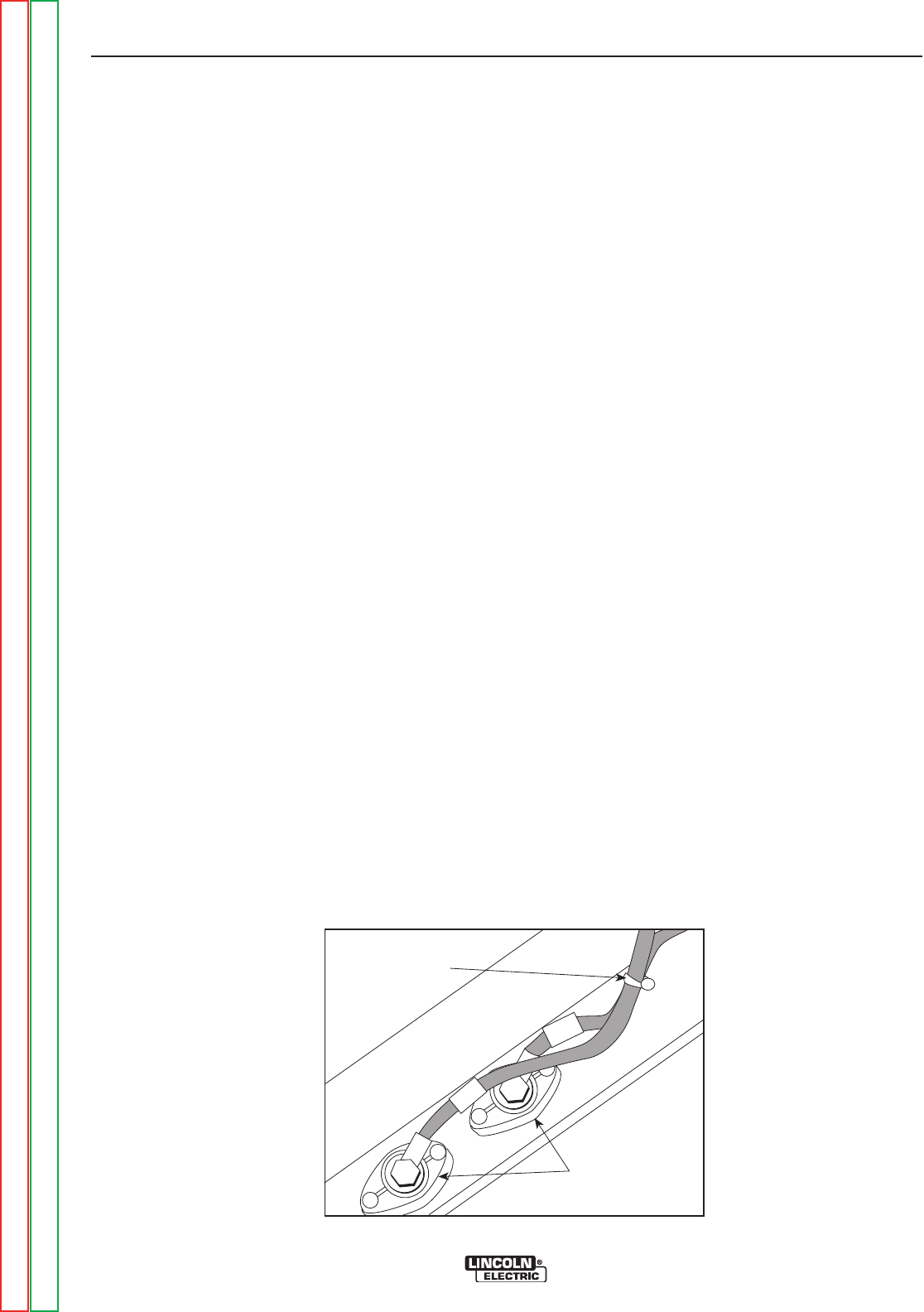
11. With the 9/16” open end wrench, remove
lead W2 from the output terminal. With
the diagonal cutters, cut the cable tie that
holds the two output leads together. Pull
lead W2 back out of the way. Screw the
bolt back into the output terminal hole
loosely for reassembly. See Figure F.11.
12. Remove the brush holder assembly. Open
the brush holder assembly cover.
Squeeze the 2 tabs and depress the cover
at the top with a screw driver or your fin-
gernail. The cover will drop open on its
bottom hinge. With the 1/4” nut driver,
remove the 2 screws that hold the brush
holder assembly in place. With the needle
nose pliers, gently remove the two leads
#201 and #202A. Note lead placement for
reassembly. Set the brush holder aside.
Pull the wires up into the control box.
13. Slide the control panel and box assembly
out of the machine cradle. Carefully pull
the wire leads down through the box as
you remove it.
FIGURE F.11 - OUTPUT LEAD LOCATION
OUTPUT
TERMINALS
W
1
W
2
TIE WRAP
Return to Section TOC Return to Section TOC Return to Section TOC Return to Section TOC
Return to Master TOC Return to Master TOC Return to Master TOC Return to Master TOC