


ROTOR RESISTANCE TEST PROCEDURE (continued)
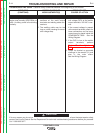
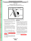
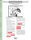
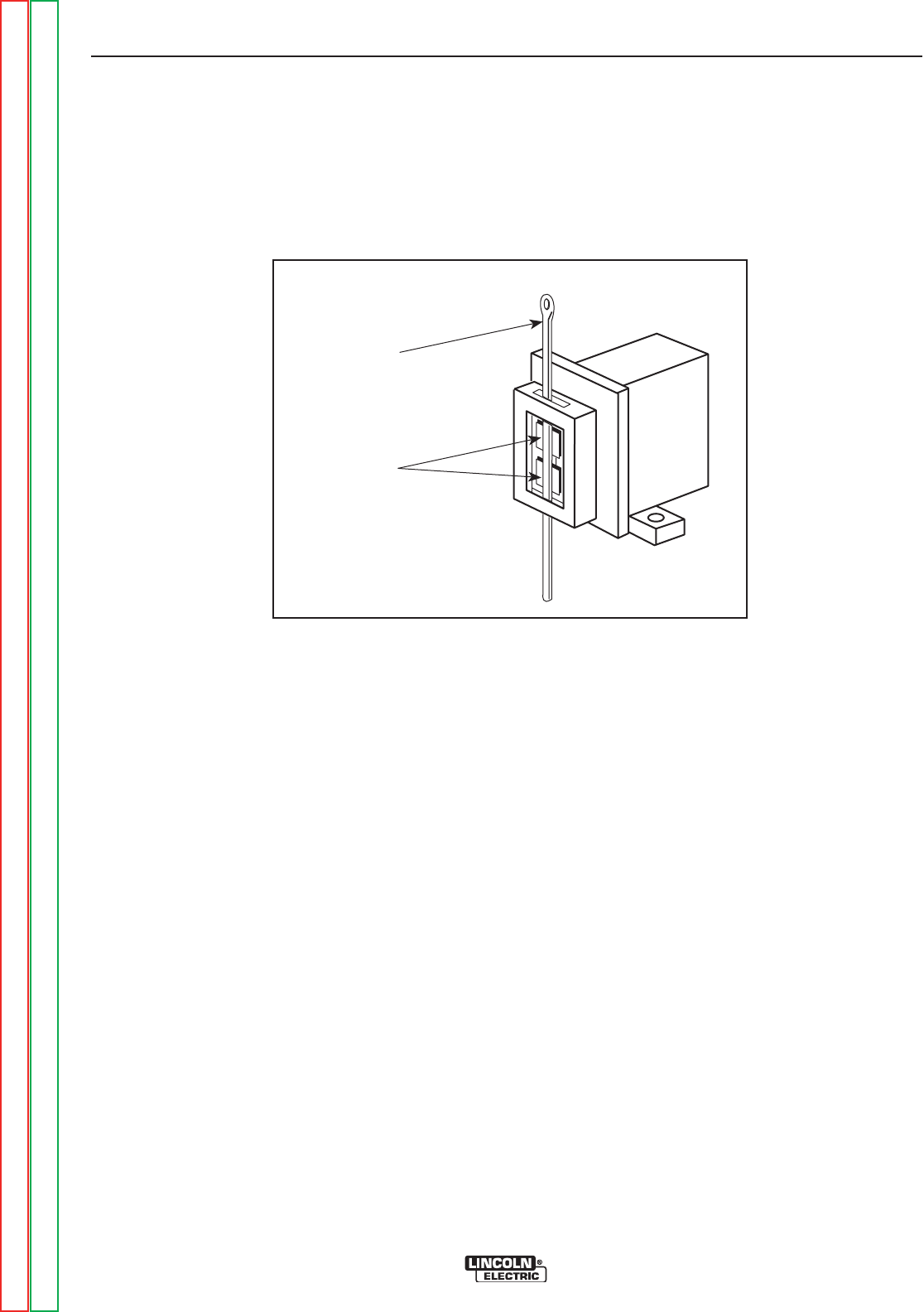
9. Reinstall the brush holder assembly after the
test. Depress the spring-loaded brushes into
the holder and slip a suitable non-metallic, fair-
ly stiff retainer through the slots at the top and
bottom of the holder. A cable tie works well;
see Figure F.3. This will hold the brushes up so
that you can easily install the holder.
10. Slip the holder into position in the generator
end bracket. Be careful not to loosen the 2
attached wires.
11. Reinstall and tighten the 2 screws with the
1/4” nut driver.
12. Slowly remove the non-metallic retainer from
the brush holder and let the brushes snap
back against the slip rings.
13. Snap the brush holder cover back into posi-
tion.
TROUBLESHOOTING AND REPAIR
F-17 F-17
POWERARC® 5500
ROTOR RESISTANCE TEST (continued)
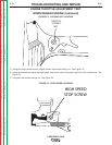
FIGURE F.3 - BRUSHES RETAINED WITH CABLE TIE
CABLE
TIE
BRUSHES
Return to Section TOC Return to Section TOC Return to Section TOC Return to Section TOC
Return to Master TOC Return to Master TOC Return to Master TOC Return to Master TOC