


TROUBLESHOOTING AND REPAIR
F-39 F-39
POWERARC® 5500
STATOR/ROTOR
REMOVAL AND REPLACEMENT PROCEDURE (continued)
6. Install the bottom two end bracket thru-
bolts.
7. Tap the end bracket with the mallet as nec-
essary to position it. Tighten the bolts to
4.5 - 5.5 ft lbs. Alternate tightening in order
to pull the assembly together evenly. As
you tighten, look through the brush housing
access door and watch the bearing to
judge end bracket movement and align-
ment.
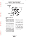
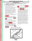
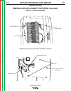
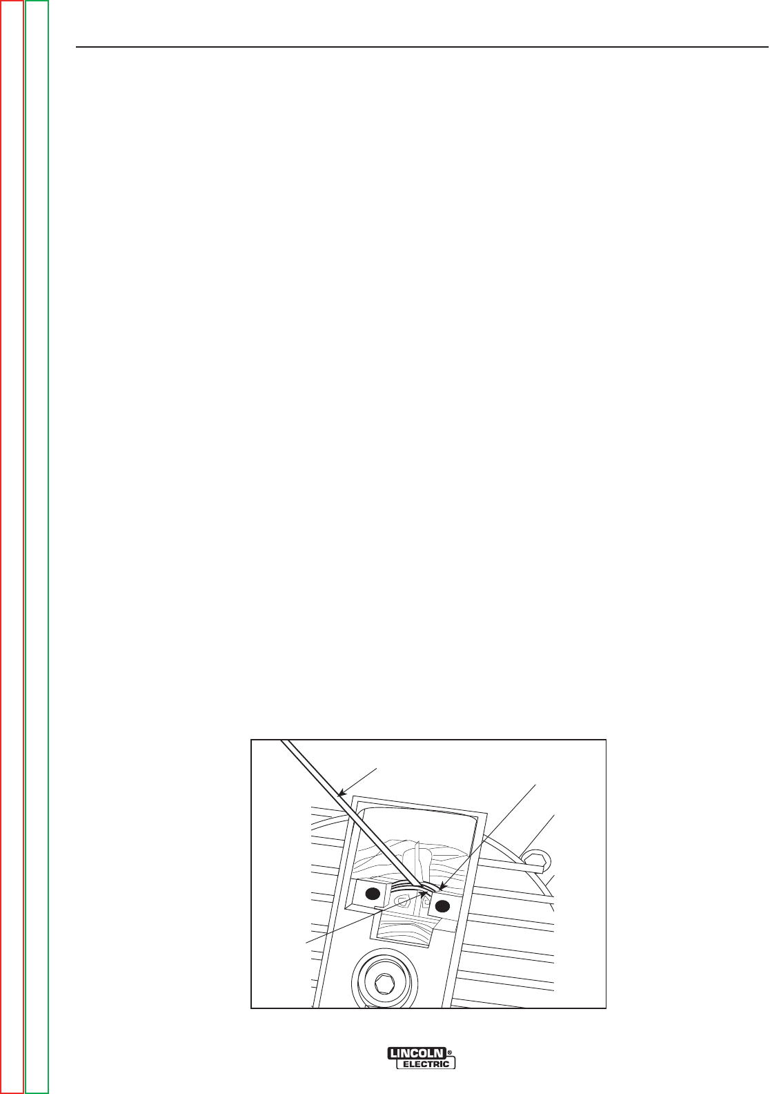
8. Check the rotor-stator air gap with the long
.010 feeler gauge. The measurement is
taken through the brush holder access
door; see Figure F14. Turn the engine with
the recoil starter rope slightly so that the
rotor “iron” is up to take the measurement.
(The rotor has two flat sides, which are not
measured for air gap.) Slide in the gauge.
Then rotate the shaft 180 degrees and mea-
sure again. If the gauge does not clear,
loosen the four end bracket thru-bolts,
reposition the end bracket, retighten the
bolts, and recheck the air gap. Repeat until
the proper .010 minimum air gap is
achieved.
9. Tighten the end bracket support nuts and
lock washers. Remove the 2 X 4 engine
support.
10. Position the control box into place.
11. Reinstall the brush holder assembly. Refer
to the Brush Removal and Replacement
Procedure.
12. Reconnect the output lead W2 to the output
terminal.
13. Install a new cable tie to hold the leads
together.
14. Reconnect the large molex plug.
15. Install the five sheet metal screws that
secure the control box to the stator frame.
Be sure to connect the green ground lead to
the screw previously removed.
16. Reconnect the flashing lead #205 to diode
D2. Secure lead in control box.
17. Using the 6 sheet metal screws previously
removed, mount the control box panel to
the control box.
18. Using the 1/2” wrench replace the 2 bolts
and star washers securing the control box
to the stator frame.
19. Carefully set the reactor in place and secure
with the two remaining bolts and star wash-
ers.
20. Reconnect the reactor leads.
21. Check all terminal connections for clear-
ance, grounding, and tightness.
22. Replace the top cover to the control box
and tighten the 8 screws.
23. Conduct the Retest After Repair
Procedure.
FIGURE F.14 - CHECKING ROTOR-STATOR AIR GAP
ROTOR
STATOR
FEELER GAUGE
Return to Section TOC Return to Section TOC Return to Section TOC Return to Section TOC
Return to Master TOC Return to Master TOC Return to Master TOC Return to Master TOC