


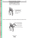
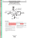
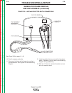
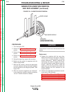
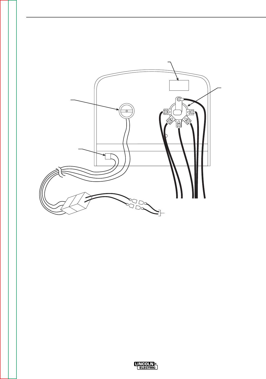
See Figure F.23 for steps 10 - 13.
10. Cut all necessary cable ties.
11. Disconnect the blue and the brown wires at the in-
line connectors. See Figure F.23 and the Wiring
Diagram.
12. Label the cables that are connected to the selector
switch. Otherwise, you will need to see the Wiring
Diagram during reassembly.
13. With the 1/2" wrench, remove the cables connect-
ed to the selector switch.
TROUBLESHOOTING & REPAIR
F-49 F-49
Classic III and IIID
Return to Section TOC Return to Section TOC Return to Section TOC Return to Section TOC
Return to Master TOC Return to Master TOC Return to Master TOC Return to Master TOC
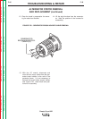
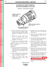
GENERATOR FRAME REMOVAL
AND REPLACEMENT (continued)
FIGURE F.23 – WIRE AND SELECTOR SWITCH CONNECTIONS
IDLER PC BOARD
FINE CURRENT
ADJUSTMENT
RHEOSTAT
SELECTOR
SWITCH
FIELD BRIDGE
IN-LINE CONNECTORS
BLUE/BROWN LEADS