


Return to Section TOC Return to Section TOC Return to Section TOC Return to Section TOC
Return to Master TOC Return to Master TOC Return to Master TOC Return to Master TOC
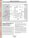
ENGINE, GENERATOR ARMATURE
AND FRAME, ALTERNATOR
STATOR AND ROTOR
EXCITATION (FLASHING)
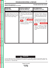
When the engine is started and running, the residual
magnetism voltage is applied to the alternator rotor
through a brush and slip ring configuration. This exci-
tation (“flashing”) voltage magnetizes the rotor lamina-
tion. The alternator rotor is connected to the armature
shaft, which is mechanically coupled to the engine.
This rotating magnet (rotor) induces a voltage in the
stationary windings of the alternator stator.
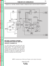
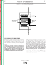
AUXILIARY AND FIELD FEEDBACK COILS
There are two isolated windings incorporated in the sta-
tor lamination assembly. One of these windings is
tapped and provides 115VAC and 230VAC of auxiliary
power to the appropriate receptacles. The other
115VAC isolated winding is rectified to a DC voltage. It
supplies field feedback voltage to the rotor. It also sup-
plies exciter voltage to the field shunt windings in the
main generator frame. This voltage is controlled by the
generator field control.
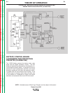
INTERPOLE AND SERIES COILS
The generator armature rotates within the magnetic
field created by the field shunt windings. A voltage is
induced in the armature and transferred, through the
armature commutator and brushes, to the series and
interpole coils. The interpole coils, which are connect-
ed in series with the positive output terminal, are locat-
ed so as to counteract any magnetic influences that
could cause distortion in the rotating field. The series
coils are designed to oppose or “buck” the DC voltage
generated by the armature.
THEORY OF OPERATION
E-5 E-5
Classic III and IIID
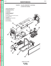
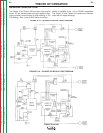
FIGURE E.3 – ENGINE, GENERATOR ARMATURE AND FRAME, ALTERNATOR STATOR AND ROTOR (CLASSIC III)
NOTE: Unshaded areas of Block Logic Diagram are the subject of discussion.