


Return to Section TOC Return to Section TOC Return to Section TOC Return to Section TOC
Return to Master TOC Return to Master TOC Return to Master TOC Return to Master TOC
TROUBLESHOOTING & REPAIR
F-51 F-51
Classic III and IIID
GENERATOR FRAME REMOVAL
AND REPLACEMENT (continued)
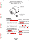
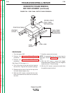
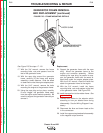
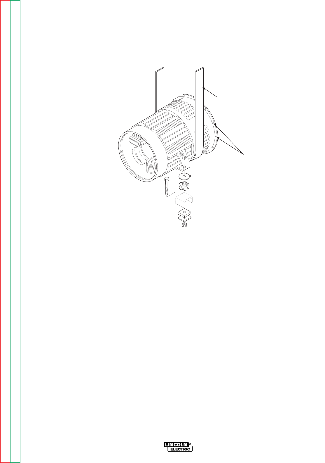
FIGURE F.25 – FRAME MOUNTING DETAILS
ENGINE/GENERATOR
MOUNTING HOLES
ROPE SLING
See Figure F.25 for steps 17 - 20.
17. With the 3/4" wrench, remove the frame
mounting bolts, nuts and spacers from the
feet of the generator frame.
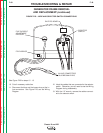
18. With the rope sling around the generator
frame, carefully lift the frame and engine
assembly a small distance. Slide the wood
or steel block under the engine adapter plate.
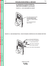
19. With the 9/16" wrench, remove the bolts
mounting the engine to the generator frame.
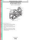
20. Using the rope sling and pry bars, carefully
lift and “wiggle” the generator frame away
from the engine and armature assembly. Be
careful to support the generator frame as you
remove it.
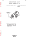
Replacement
21. Support the generator frame with the rope
sling. Mount the generator frame to the
engine and armature assembly. Before
removing the rope sling, be careful to sup-
port the generator frame with the wood or
steel block under the engine adapter plate.
With the 9/16" wrench, install the bolts that
attach the generator frame to the engine.
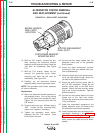
22. With the 3/4" wrench, install the frame
mounting bolts, nuts, and spacers to the feet
of the generator frame. See Figure F.25.
23. Install the case front to the welder frame.
See
steps 14 - 16.
24. Connect the cables to the selector switch
according to how you labeled them during
disassembly. See the Wiring Diagram if nec-
essary.
25. Reconnect the blue and brown leads at the
in-line connectors.
26. Install the copper strap/reed switch assembly
to the negative output terminal.