


TROUBLESHOOTING & REPAIR
F-31 F-31
Classic III and IIID
Return to Section TOC Return to Section TOC Return to Section TOC Return to Section TOC
Return to Master TOC Return to Master TOC Return to Master TOC Return to Master TOC
6. If either of these readings is incorrect, adjust the
throttle as follows:
Adjust High Idle
a. Make sure there is no load on the machine.
b. Set the Idler switch to the HIGH position.
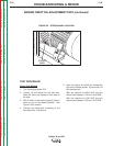
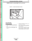
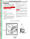
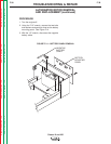
c. Locate the governor on the left side of the engine.
See
Figure F.12.
d. Using the 3/8” wrench to turn the adjustment screw
and locking nut, adjust the high idle speed to
between 1780 - 1810 RPM. It may not be neces-
sary to remove the seal. See
Figure F.12.
e. If further adjustments are necessary, consult the
Engine Manual.
Adjust Low Idle
a. Make sure there is no load on the machine.
b. Set the Idler switch to AUTO and wait for the
engine to change to low idle speed.
c. Check the alignment of the idler rod so that the
plunger can move freely.
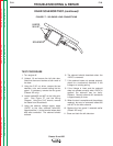
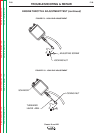
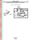
d. Using the 7/16” wrench, loosen the idler rod lock-
ing nut. This is located on the idler rod between
the carburetor ball joint and the idler solenoid. See
Figure F.13.
e. Rotate the carburetor shaft, and while holding it
against the idle stop screw on the carburetor,
adjust this screw to obtain low idle RPM (1325
RPM).
f. With the idler plunger fully seated, adjust idle
speed by rotating the threaded rod in the ball joint.
Lock the position by tightening the nut with the ball
joint.
g. RPM should be 1325-1475 RPM. If necessary,
adjust the idle screw to increase the idle speed by
a maximum of 50 RPM.
FREQUENCY COUNTER METHOD
1. Plug the frequency counter into one of the 115
VAC auxiliary receptacles.
2. Start the engine and check the frequency counter.
At HIGH IDLE (1800 RPM), the counter should
read 60 Hz. At LOW IDLE (1400 RPM), the
counter should read 47 Hz. Note that these are
median measurements; hertz readings may very
slightly above or below.
3. If either of the readings is incorrect, adjust the
throttle as follows.
Adjust High Idle
a. Make sure there is no load on the machine.
b. Set the Idler switch to the HIGH position.
c. Locate the governor on the left side of the engine.
See
Figure F.12.
d. Using the 3/8” wrench to turn the adjustment screw
and locking nut, adjust the high idle speed to
between 1780 - 1810 RPM. It may not be neces-
sary to remove the seal. See
Figure F.12.
e. If further adjustments are necessary, consult the
Engine Manual.
Adjust Low Idle
a. Make sure there is no load on the machine.
b. Set the Idler switch to AUTO and wait for the
engine to change to low idle speed.
c. Check the alignment of the idler rod so that the
plunger can move freely.
d. Using the 7/16” wrench, loosen the idler rod lock-
ing nut. This is located on the idler rod between
the carburetor ball joint and the idler solenoid. See
Figure F.13.
e. Rotate the carburetor shaft, and while holding it
against the idle stop screw on the carburetor,
adjust this screw to obtain low idle RPM (1325
RPM).
f. With the idler plunger fully seated, adjust idle
speed by rotating the threaded rod in the ball joint.
Lock the position by tightening the nut with the ball
joint.
g. RPM should be 1325-1475 RPM. If necessary,
adjust the idle screw to increase the idle speed by
a maximum of 50 RPM.