


ELECTRICAL DIAGRAMS
G-11 G-11
CLASSIC III/IIID
Return to Section TOC Return to Section TOC Return to Section TOC Return to Section TOC
Return to Master TOC Return to Master TOC Return to Master TOC Return to Master TOC
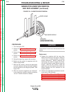
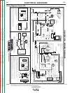
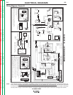
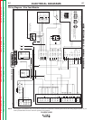
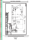
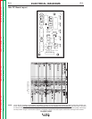
Idler PC Board Layout
NOTE: Lincoln Electric assumes no responsibility for liablilities resulting from board level troubleshooting. PC Board repairs will invalidate your
factory warranty. Individual Printed Circuit Board Components are not available from Lincoln Electric. This information is provided
for reference only. Lincoln Electric discourages board level troubleshooting and repair since it may compromise the quality of the design
and may result in danger to the Machine Operator or Technician. Improper PC board repairs could result in damage to the machine.
CAPACITORS = MFD/VOLTS
RESISTORS = OHMS
IDLER
ENGINE
WELDER
R20
R17
R15
R9
R13
R1
R21
R16
R12
R2
R7
R4
R3
R14
R18
R6
R19
R5
C9
C1
C8
C7
C5
C3
C2
C10
C6
D5 DZ3
D8
D7
D3
D2
D1
DZ2
X1 X2
R11
Q1
DZ1
C4
B210 B212 B211 B209 B213
R8
Q2
R10
M13708-3