


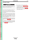

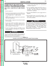
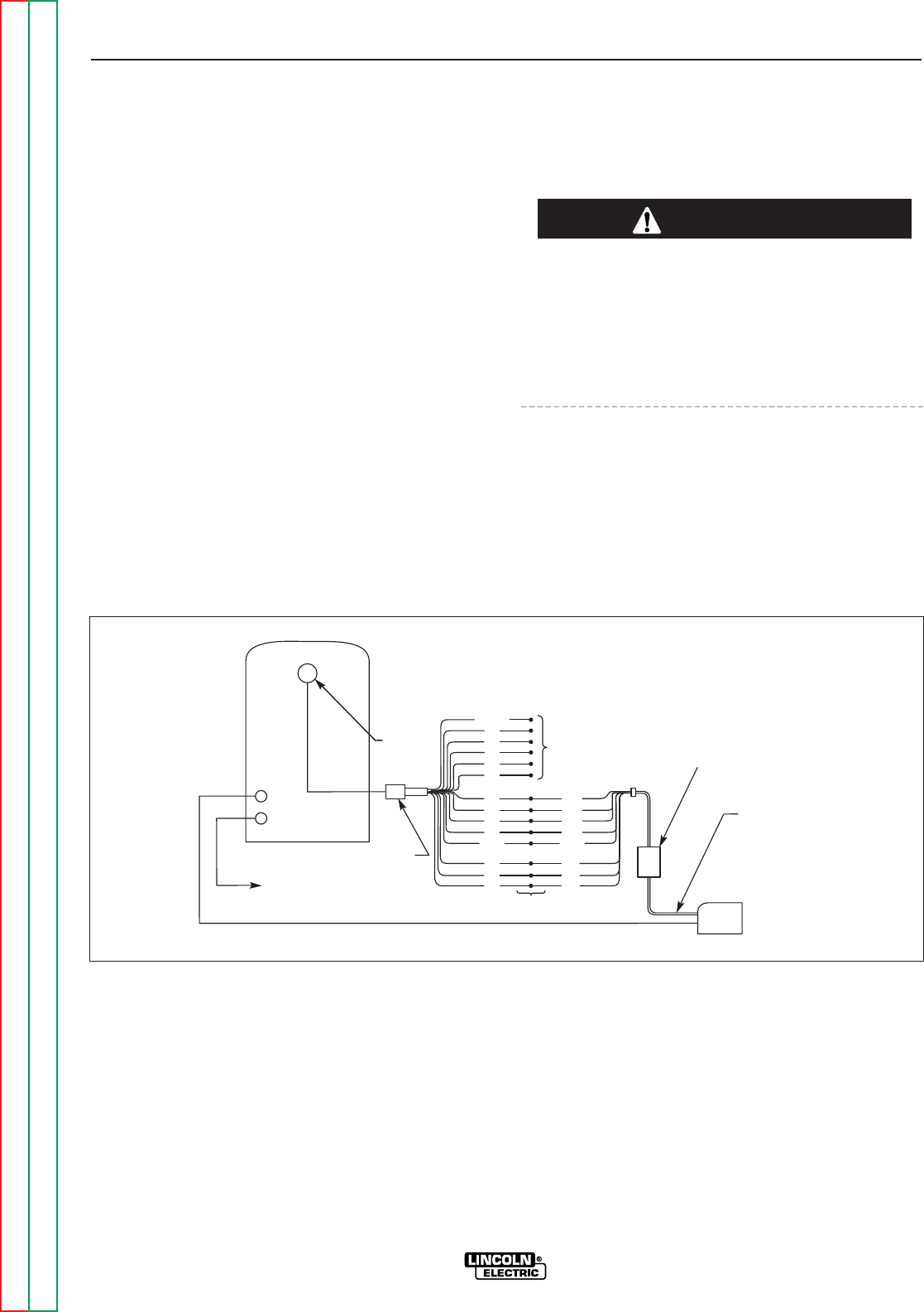
CONNECTION OF THE LN-25 TO THE
CLASSIC III OR CLASSIC IIID (EQUIPPED
WITH K623-1 WIRE FEED MODULE)
USING K867 UNIVERSAL ADAPTER
(SEE FIGURE C.3.)
1. Shut the welder off.
2. Connect the electrode cable from the LN-25 to the
“+” terminal of the welder. Connect the work cable
to the “CV-” terminal of the welder.
NOTE: Welding cable must be sized for current and
duty cycle of application.
NOTE: Figure C.3 shows the electrode connected for
positive polarity. To change polarity, shut the welder
off and reverse the electrode and work cables at the
Classic III or Classic IIID output terminals. Reverse the
LN-25 polarity switch.
3. Connect the K867 Universal adapter to the K433
cable and the 14 pin amphenol of the Classic III or
Classic IIID as indicated in Figure C.3. Mount the
K433 to the welder according to instructions
included with the K433 kit.
4. Connect the K432-L cable to the LN-25 equipped
with the K431-1 remote output control kit.
5. Place the IDLER switch in the “HIGH” position.
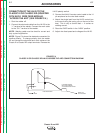
Any increase of the high idle engine RPM by changing
the governor setting or overriding the throttle linkage
will cause an increase in the AC auxiliary voltage. If
this voltage goes over 140 volts, wire feeder control
circuits may be damaged. The engine governor set-
ting is preset at the factory — do not adjust above
RPM specifications listed in this manual.
6. Adjust wire feed speed and voltage at the LN-25.
ACCESSORIES
C-6 C-6
Classic III and IIID
Return to Section TOC Return to Section TOC Return to Section TOC Return to Section TOC
Return to Master TOC Return to Master TOC Return to Master TOC Return to Master TOC
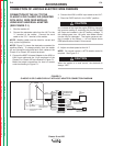
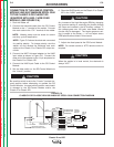
CAUTION
Splice Leads and Insulate
Insulate Each
Unused Lead
Individually
TO
WORK
14 PIN
AMPHENOL
SPARE
82
81
42
41
21
32
31
32
31
2 2
4 4
75
76
77
75
76
77
GND GND
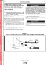
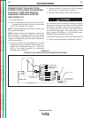
K432-"L" CABLE
K433
LN-25 WIRE FEEDER
WITH K431 OPTION
K867 UNIVERSAL
ADAPTER PLUG
ELECTRODE CABLE
CV-
+
FIGURE C.3
CLASSIC III OR CLASSIC IIID/LN-25 CONNECTION DIAGRAM