


OM-203 185 Page 53
Trouble Remedy
If display flashes no.io again, or if
0-10 V output card fails.
Remove 2408 control from its housing by pressing locking tabs outward slightly on sides of control and pulling
control forward. Look for add−on PC card in back of controller, and remove PC card. Reinstall 2408 control
into housing being careful not to damage locking tabs on housing. Disable output card function as follows:
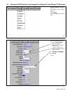
Goto ConF, IA ConF (Module 1 Config). See Section 8-5-4.
Change id dc.OP to id nonE.
Scroll to Exit no and change it to Exit YES, and the controller will reset automatically.
Set power source panel / remote switch to panel position and set desired maximum output. The control will
operate in an on / off mode (at target temp + over temp alarm value).
The over temp alarm value is set in Goto Ful, AL LiSt, IdHi.
Obtain a replacement 0-10 V isolated card.
Output stops when green Run
button is released.
Replace Hold button.
Temperature readings go down
instead of up.
Check for reversed red (−) and yellow (+) leads in 2-pin thermocouple, and correct if necessary.
Temperature readings do not rise. Check for a short between thermocouple wires.
Temperatue does not change in
ramp segment.
Change the ramp rate for that segment in the Program List.
Fault/Limit light is on.
Parameter Display will indicate either “Coolant Flow Error” or “PS Limit”.
“Coolant Flow Error” − ensure that cooler is plugged in and turned on.
For 25 kW system, ensure receptacle switch is on.
Check coolant level in reservoir, and add coolant if necessary.
Check filter on cooler and replace, if necessary.
Verify that coolant “IN” and “OUT” hoses are connected to the correct fittings.
Check alignment of center pins in plastic quick disconnect fittings.
Be sure that coolant jumpers are connected properly.
“PS Limit” indicates the power source will run at less than full output.
Verify panel/remote switch on power source is in Remote position.
Turn down dial on front panel of power source until light goes out or
To obtain full output, adjust the coil to get more coupling into the part.
Check set-up parameters.
If Volts setting is greater than 650, add a turn to the heating coil.
Current Source fault.
Remove a turn from the heating coil.
Power/Volts equals Real Current, Real Current must be kept under 60 A.
2408 Controller displays dwell
before 10 degree window is
reached
Check that Hold Back setting is in Band, display will read Hb bAnd (see Section 8-5-3, Goto Ful, ProG
LiSt).
reached.
Check that Hold Back Units equals 10 F, display will read Hb U 10 (see Section 8-5-3, Goto Ful, ProG
LiSt).
Parameter display does not
operate, but 2408 Temperature
Controller and 5100V Recorder
displays do operate.
See Section 8-3A.
2408 Temperature Controller
display does not operate, but 5100V
Recorder display does operate.
See Section 8-3B.
5100V Recorder does not turn on,
but 2408 Temperature Controller
does turn on.
See Section 8-3C.
Flow/Limit light does not illuminate
when cooler is turned off.
See Section 8-3D.
Heat On light does not display when
power source is supplying output.
See Section 8-3E.
Output does not start when Run
button is pressed.
See Section 8-3F.
Pressing Power Source Select
button on rear of IH/TS does not
change selection.
See Section 8-3G.
5100V Recorder displays Channel
Error.
See Section 8-3H.