


OM-880 Page 7
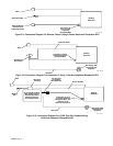
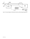
18. Disconnect leads 623 and 625 at insulated fric-
tion terminals, and connect these leads to the
matching leads from the CV-2 panel (see Figure
3-4).
19. Connect lead 632 from Current Regulator box to
lead 632 from CV-2 panel (see Figure 3-4).
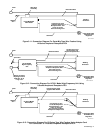
20. Connect lead 49 from CV-2 panel to terminal at
AUTO IDLE switch S4 on BIG 30 DIESEL, BIG
40 DIESEL, BIG 40G, and BIG 50 DIESEL mod-
els or to terminal at Engine Control switch S1 on
BIG 30A DIESEL models where existing lead 49
is connected as follows:
a. Disconnect existing lead 49 from S4 or S1.
b. Reconnect lead 49 (from Step a) to piggyback
connector on lead 49 from CV-2 panel.
c. Install piggyback connector onto S4 or S1 ter-
minal where lead 49 was removed in Step a.
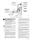
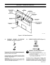
21. Connect lead 42 from CV-2 panel to the rear of
the equipment grounding terminal located in the
lower right portion of the front control panel on the
welding generator.
IMPORTANT: Be sure that all existing leads remain
connected to the equipment grounding terminal when
connecting lead 42 from CV-2 panel.
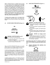
22. Connect leads 110 from CV-2 panel circuit
breaker CB5 as follows:
For welding generators not equipped with auxil-
iary power circuit breaker CB3, proceed as fol-
lows;
a. Locate and disconnect the friction terminal con-
nection between leads 110 and 112 near the
rear of the 120V duplex receptacle.
b. Connect the insulated male friction terminal on
CB5 lead 110 to female friction terminal on end
of lead 110 disconnected in Step a.
c. Connect remaining CB5 lead 110 to lead 112
disconnected in Step a.
For welding generators equipped with auxiliary
power circuit breaker CB3, proceed as follows:
a. Disconnect existing lead 110 from CB3.
b. Connect the insulated male friction terminal on
CB5 lead 110 to female friction terminal on end
of lead 110 disconnected in Step a.
c. Connect remaining CB5 lead 110 to CB3 termi-
nal where lead 110 was disconnect in Step a.
23. Connect the two leads 100 from terminal strip 3T
on CV-2 panel to lead 100 at the 120V duplex re-
ceptacle as follows:
a. Locate and disconnect the friction terminal con-
nection on lead 100 near the rear of the 120V
duplex receptacle.
b. Connect the insulated female friction terminal
on 3T lead 100 with the male friction terminal on
the end of lead 100 separated in Step a.
c. Connect the remaining male friction terminal on
3T lead 100 with the female friction terminal on
the end of the remaining lead 100 separated in
Step a.
24. Tape or tie leads from CV-2 components to exist-
ing wiring harness to maintain lead dress and to
avoid contact with hot or moving parts.