


OM-880 Page 9
the welding power source. To connect the Remote Con-
tactor and/or Amperage or Voltage Control to the RE-
MOTE-5 receptacle, align keyway, insert plug from the
Remote Control, and rotate threaded collar fully clock-
wise.
E
AD
BC
S-0005
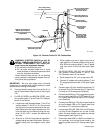
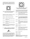
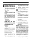
Figure 3-6. Front View Of 5-Socket Amphenol Re-
ceptacle With Socket Designations
Receptacle RC3 socket connections to the welding
power source control circuitry are as follows:
Socket A: Contactor control switch connection.
Socket B: Contactor control switch connection.
Socket C: Amperage or voltage control connection
(maximum side).
Socket D: Amperage or voltage control connection
(minimum side).
Socket E: Amperage or voltage control connection
(wiper contact).
IMPORTANT: Use only one CV-2 receptacle at a time
for remote current and/or voltage control or welding gen-
erator may not work properly.
3-3. REMOTE-14 RECEPTACLE INFORMATION
AND CONNECTIONS (Figures 3-7 And 4-1)
REMOTE-14
The 14-socket REMOTE-14 receptacle RC4 provides a
junction point for connecting a Remote Amperage/Volt-
age Control and/or a Remote Contactor Control or a
wire feeder providing switch closure for contactor con-
trol to the control circuitry of the welding generator. To
make connections, align keyway, insert plug fully into re-
ceptacle, and rotate threaded collar clockwise.
AJ
B
K
I
C
L
NH
D
M
G
E
F
S-0004
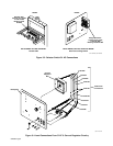
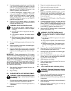
Figure 3-7. Front View Of 14-Socket Amphenol
Receptacle With Socket Designations
The command signals required and the output signals
available at the sockets of receptacle RC4 by means of
the welding generator control circuitry are as follows:
Socket A: Up to 10 amperes of 24 volts ac 60 Hz with
respect to socket G (circuit common), pro-
tected by circuit breaker CB6.
Socket B: Weld contactor control for 24 volts ac wire
feeders providing contact closure to socket
A.
Socket C: 0 to +10 volts dc with respect to Socket D;
reference voltage for output command sig-
nal depends on the AMPERAGE & VOLT-
AGE ADJUSTMENT control setting on the
unit.
Socket D: Control circuit common for remote control
device.
Socket E: Output command signal to wiper of remote
control potentiometer, 0 volts equals ma-
chine minimum; +10 volts equals machine
maximum.
Socket F: Not used.
Socket G: 24 and 120 volts ac circuit common.
Socket H: Not used.
Socket I: Up to 10 amperes of 120 volts ac 60 Hz with
respect to socket G (circuit common), pro-
tected by circuit breaker CB5.
Socket J: Weld contactor control for 120 volts ac wire
feeders providing contact closure to socket
I.
Socket K: Machine chassis.
Socket L: Not used.
Socket M: Not used.
Socket N: Not used.
IMPORTANT: Use only one CV-2 receptacle at a time
for remote current and/or voltage control or welding gen-
erator may not work properly.