


OM-880 Page 13
SECTION 4 – OPERATOR CONTROLS
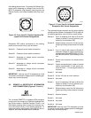
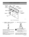
SC-111 216-A
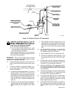
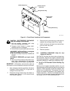
Circuit
Breaker CB5
Remote-14
Receptacle RC4
Circuit Breaker CB6
Output/Contactor
Switch S10
Current Control
Switch S11
Constant Voltage (CV)/
Constant Current(CC)
Switch S12
Prepunched Hole
For Securing
Key Chain
Remote-5
Receptacle RC3
Receptacle
Dust Cups
AC/DC Selector
Switch S1
CV-2 Control
Panel
Figure 4-1. CV-2 Panel Components
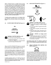
4-1. CONSTANT VOLTAGE (CV)/CONSTANT
CURRENT (CC) SWITCH (Figure 4-1)
CC
CV
Placing this switch in the CC position causes the weld-
ing generator to provide weld output for processes re-
quiring a constant current output.
Placing this switch in the CV position causes the welding
generator to provide weld output for processes requiring
a constant voltage output.
IMPORTANT: When using the CV mode, place the AM-
PERE RANGES switch on the welding generator in the
maximum amperage range position.
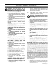
4-2. CURRENT CONTROL SWITCH (Figure 4-1)
PANEL
A
V
CURRENT
CONTROL
REMOTE
WARNING: ELECTRIC SHOCK can kill.
• Do not touch live electrical parts.
• Do not touch weld output terminals when
contactor is energized.
• Do not touch welding wire or electrode and
work clamp at the same time.
If remote current or voltage control is desired, make
connections to either the REMOTE-5 or REMOTE-14
receptacle as instructed in Section 3-2 or 3-3. Place the
CURRENT CONTROL switch in the REMOTE position.