


OM-880 Page 5
SB-112 688-A
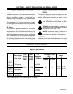
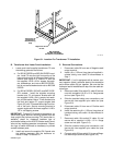
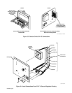
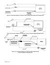
Left Front Upright When
Viewed From Front
Of Control Panel
Electrode (Negative)
Weld Output Terminal
Weld Output
Terminal Assembly
Work (Positive)
Weld Output
Terminal
Bimetal Jumper
Bar-Copper Side
Of Bar Against
Terminal Surface
Cable 19Selector
Switch S1
Cable Lug Connection
With Tubing And Ties
Rear View (Inside)
Of Lower Front Panel
Cable 28
Cable 30
Cable 30 From Negative
Weld Output Terminal
And Black Voltmeter Lead,
If Applicable
Cable 19 From Positive
Weld Output Terminal
Figure 3-2. Selector Switch S1 DC Connections
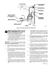
WARNING: ELECTRIC SHOCK can kill; BI-
METAL JUMPER BAR CONTACT WITH IN-
TERNAL COMPONENTS can cause per-
sonal injury and equipment damage.
• Do not touch live electrical parts.
• Do not allow bimetal jumper bar to touch
metal surfaces or internal components other
than the intended connection.
Route bimetal jumper bar so it is not touching
other surfaces or components between connec-
tion points during operation.
IMPORTANT: Be sure that copper side of bimetal
jumper bar is in contact with copper surface of output
terminal when making connections.
10. Connect bimetal jumper bar from switch S1 to
rear of Positive weld output terminal (see Figure
3-2).
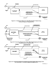
11. For BIG 30 DIESEL and BIG 30A DIESEL mod-
els, connect cables 17 and 27 from CV-2 Selector
switch S1 as follows:
a. Locate and install supplied cables 17 and 27 on
existing cables 17 and 27 on S1. Be sure that
the lugs on the nonconnected ends of the sup-
plied cables have the larger diameter hole. Se-
cure the cable lug connections using the sup-
plied 1/4-20 x 3/4 in. screws, flat washers (4),
and nuts.
b. Slide a 6 in. (152 mm) long piece of supplied in-
sulated tubing over each connection. Secure in-
sulated tubing with the supplied nylon cable
ties.
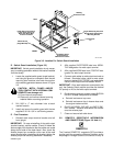
c. Route cables over top of stator barrel and to
right side of unit. Connect cables from S1 to rec-
tifier SR3 with existing cables 17 and 27 below
right rear corner of the fuel tank (see Figure
3-3).
12. For BIG 40 DIESEL, BIG 40G, and BIG 50 DIE-
SEL models, connect cables 17 and 27 from
CV-2 Selector switch S1 as follows:
a. Route cables from S1 up to range switch S3.
b. Connect S1 cables with existing cables 17 and
27 at appropriate terminals on S3 (see Figure
3-3).
13. Connect lead 100 from installed transformer T2
to terminal D on CV-2 terminal strip 3T (see Parts
List view for CV-2 component locations).
14. Connect lead 205 from T2 to piggyback connec-
tor on existing lead 205 at CV/CC switch S12 on
CV-2 panel (see Parts List view for CV-2 compo-
nent locations).
15. Connect lead 206 from T2 to the unused terminal
at circuit breaker CB6 on CV-2 panel (see Parts
List view for CV- component locations).
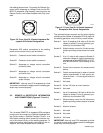
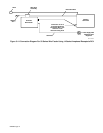
16. Locate leads 623, 625, 628, 632, and 634 hang-
ing from Current Regulator box on rear of front
panel. Cut and remove nylon cable ties holding
leads together (see Figure 3-4).
17. Disconnect leads 628 and 634 at insulated fric-
tion terminals, and connect these leads to the
matching leads from the CV-2 panel (see Figure
3-4).