


OM-880 Page 16
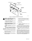
10. If remote contactor control is not used, place the
CV-2 OUTPUT/CONTACTOR switch in the ON
position. If remote contactor control is to be used,
place the OUTPUT/CONTACTOR switch in the
REMOTE position (see Section 4-3).
11. If remote amperage or voltage control is not
used, place the CV-2 CURRENT CONTROL
switch in the PANEL position. If remote amper-
age or voltage control is to be used, place the
CURRENT CONTROL switch in the REMOTE
position (see Section 4-2).
12. Place the AC/DC Selector switch in the proper
position as determined by the selected welding
process (see Section 4-4).
WARNING: ELECTRIC SHOCK can kill.
• Do not use AC output in damp areas, if
movement is confined, or if there is a danger
of falling.
• Use AC output ONLY if required for the weld-
ing process.
• If AC output is required, use remote output
control.
• Read and follow Safety Precautions at be-
ginning of welding generator Owner’s Manu-
al.
13. Turn on shielding gas supply at the source, if ap-
plicable.
14. Start the engine as instructed in the welding gen-
erator Owner’s Manual.
15. Place the AUTO IDLE control switch in the OFF
position or the Engine Control switch in the RUN
position (see welding generator Owner’s Man-
ual).
IMPORTANT: Power requirements by CV-2 compo-
nents will cause the welding generator engine to operate
at weld rpm continuously in the CV mode if the AUTO
IDLE control switch is placed in the ON position or the
Engine Control switch is placed in the AUTO IDLE posi-
tion. Placing the AUTO IDLE control switch in the OFF
position or the Engine Control switch in the RUN posi-
tion will prevent mistaking unit operation as a malfunc-
tion in the Auto Idle circuitry.
16. Wear welding helmet with proper filter lens ac-
cording to ANSI Z49.1.
17. Begin welding.
5-2. SHIELDED METAL ARC WELDING (SMAW)
WARNING: Read and follow safety informa-
tion at beginning of entire Section 5 before
proceeding.
1. Be sure that the welding generator has been pre-
pared as instructed in its Owner’s Manual.
2. Install and connect CV-2 according to Section 3,
if applicable.
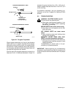
3. Wear dry insulating gloves and clothing.
4. Select and obtain proper electrode.
5. Connect work clamp to clean, bare metal at work-
piece.
6. Rotate the AMPERE RANGES switch and AM-
PERAGE AND VOLTAGE ADJUSTMENT con-
trol to the desired position (see welding generator
Owner’s Manual).
7. Place the CV-2 CV/CC switch in the CC position
(see Section 4-1).
8. If remote amperage control is not used, place the
CV-2 CURRENT CONTROL switch in the
PANEL position. If remote amperage control is to
be used, place the CURRENT CONTROL switch
in the REMOTE position (see Section 4-2).
9. Place the AC/DC Selector switch in the desired
position (see Section 4-4).
WARNING: ELECTRIC SHOCK can kill.
• Do not use AC output in damp areas, if
movement is confined, or if there is a danger
of falling.
• Use AC output ONLY if required for the weld-
ing process.
• If AC output is required, use remote output
control.
• Read and follow Safety Precautions at be-
ginning of welding generator Owner’s Manu-
al.
10. Place the CV-2 OUTPUT/CONTACTOR switch
in the ON position (see Section 4-3).
11. Start the engine as instructed in the welding gen-
erator Owner’s Manual.
12. Place the AUTO IDLE control switch or Engine
Control switch in the desired position (see weld-
ing generator Owner’s Manual).
13. Insert electrode into holder.
14. Wear welding helmet with proper filter lens ac-
cording to ANSI Z49.1.
15. Begin welding.
5-3. GAS TUNGSTEN ARC WELDING (GTAW)
WARNING: Read and follow safety informa-
tion at beginning of entire Section 5 before
proceeding.
1. Be sure that the welding generator has been pre-
pared as instructed in its Owner’s Manual.
2. Install and connect CV-2 according to Section 3,
if applicable.
3. Install torch/gun according to the manufacturer’s
Owner’s Manual.
4. Make all necessary shielding gas and water (if
applicable) connections.