


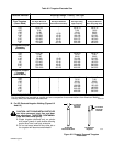

OM-880 Page 22
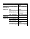
Table 6-3. Troubleshooting
TROUBLE PROBABLE REMEDY
Wire feeder inoperative. Circuit breaker CB5 or CB6 open. Reset CB5 or CB6 according to
Section 6-2.
No remote control of con- OUTPUT/CONTACTOR switch S10 Place S10 in the REMOTE position
tactor; open-circuit voltage in the ON position. (see Section 4-3).
present all the time when
engine is running.
No contactor control; no CV-2 not correctly installed if done as Review Section 3 and check all
weld output; no open- a field kit. connections.
circuit voltage.
Incorrect or poor connections to Check and secure connections (see
REMOTE-5 receptacle RC3 or Sections 3-2 and 3-3).
REMOTE-14 receptacle RC4.
Remote Contactor Control device. Check and repair or replace remote
device as necessary.
Contactor control circuit board PC3. Replace PC3 according to Section 6-3.
Improper current or volt- Remote current and/or voltage control Use only one CV-2 receptacle for
age level adjustment with device connected at both receptacles. remote current or voltage control.
remote control device.
No control of voltage; CV-2 not correctly installed if done as a Review Section 3 and check all
maximum or very low or field kit (cables 19 and 30 from rectifier connections, especially cables 19 and
no open-circuit voltage SR3 reversed to Selector Switch cables). 30.
present.
Incorrect or poor connections to Check and secure connections (see
REMOTE-5 receptacle RC3 or Sections 3-2 and 3-3).
REMOTE-14 receptacle RC4.
CV/CC switch S12 in CC position. Place S12 in the CV position (see
Section 4-1).
Remote Voltage Control device. Check and repair or replace remote
device as necessary.
Voltage control circuit board PC4. Replace PC4 according to Section 6-3.