


OM-880 Page 14
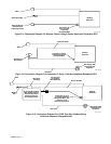
When a Remote Current or Voltage Control is being
used, the remote control functions as a fine amperage
or voltage adjustment for the AMPERAGE & VOLTAGE
adjustment control setting of the welding generator. For
example: If the AMPERAGE & VOLTAGE adjustment
control on the welding generator is set at midrange, the
Remote Current or Voltage Control will provide (from
minimum to maximum adjustment) fine amperage or
voltage adjustment of one half of the welding generator
output for the amperage range selected on the AM-
PERE RANGES switch. For complete remote control of
the output, rotate the front panel AMPERAGE & VOLT-
AGE control to the maximum position.
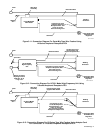
If remote current or voltage control is not desired, place
the CURRENT CONTROL switch in the PANEL posi-
tion. Only the front panel controls will then adjust the
output.
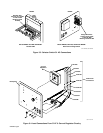
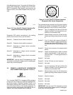
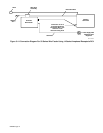
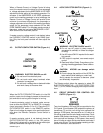
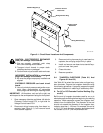
4-3. OUTPUT/CONTACTOR SWITCH (Figure 4-1)
ON
OUTPUT/
CONTACTOR
REMOTE
WARNING: ELECTRIC SHOCK can kill.
• Do not touch live electrical parts.
• Do not touch weld output terminals when
contactor is energized.
• Do not touch welding wire or electrode holder
and work clamp at the same time.
When the OUTPUT/CONTACTOR switch is in the ON
position, open-circuit voltage is present at the weld out-
put terminals for as long as the engine is running.
If remote contactor control is desired, make connec-
tions to either the REMOTE-5 or REMOTE-14 recepta-
cle as instructed in Section 3-2 or 3-3. Place the OUT-
PUT/CONTACTOR switch in the REMOTE position.
Open-circuit voltage is present at the weld output termi-
nals when the Remote Contactor Control switch is
closed.
If remote contactor control is not desired, place the
OUTPUT/CONTACTOR switch in the ON position.
Open-circuit voltage will be available at the weld output
terminals whenever the engine is running.
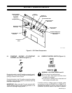
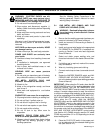
4-4. AC/DC SELECTOR SWITCH (Figure 4-1)
AC
ELECTRODE POS.
(+)
(–)
ELECTRODE
NEG.
WARNING: ELECTRIC SHOCK can kill.
• Do not use AC output in damp areas, if
movement is confined, or if there is a danger
of falling.
• Use AC output ONLY if required for the weld-
ing process.
• If AC output is required, use remote output
control.
• Read and follow Safety Precautions at be-
ginning of welding generator Owner’s Manu-
al.
CAUTION: ARCING can damage switch
contacts.
• Do not change the position of the AC/DC Se-
lector switch while welding or under load.
Arcing causes the contacts to become pitted
and eventually inoperative.
The Selector switch allows the operator to select DC
ELECTRODE NEGATIVE (–), DC ELECTRODE POSI-
TIVE (+), or AC without changing weld output connec-
tions.
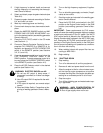
4-5. CIRCUIT BREAKER FOR CONTROL CIR-
CUITRY (Figure 4-1)
CIRCUIT
BREAKER
Two circuit breakers, CB5 and CB6, are provided on the
CV-2 panel. Circuit breaker CB5 protects the primary of
transformer T2 and the unit wiring from overload and
damage. If CB5 opens, there would be no 115 volts ac or
24 volts ac output and the wire feeder would stop. Circuit
breaker CB6 protects transformer T2 and the unit wiring
from overload and damage. If CB6 opens, there would
be no 24 volts ac output and the wire feeder would stop if
it was using 24 vac. For circuit breaker resetting and ad-
ditional information, see Section 6-2.