


OM-880 Page 4
ST-145 421
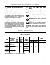
Transformer T2
Installed Onto
Base Mounting
Strip
Right Front Cover
Of Unit
BIG 30 DIESEL
And BIG 30A DIESEL
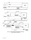
Transformer T2 Installation
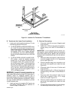
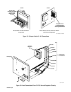
Figure 3-1. Location For Transformer T2 Installation
B. Transformer And Lower Panel Installation
1. Locate and install supplied transformer T2 onto
the welding generator as follows:
a. For BIG 30 DIESEL and BIG 30A DIESEL mod-
els: Install T2 onto the right front portion of the
base mounting strip at the prepunched hole lo-
cations (see Figure 3-1). Secure T2 with the
four supplied 1/4-20 x 3/4 in. screws, flat wash-
ers, lockwashers, and nuts on BIG 30 DIESEL,
but do not use flat washers and nuts on BIG 30A
DIESEL.
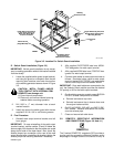
b. For BIG 40 DIESEL, BIG 40G, and BIG 50 DIE-
SEL models: Install the supplied mounting
bracket onto T2, and secure bracket with the
four supplied 1/4-20 x 3/4 in. screws, lock wash-
ers, and flat washer. Mount T2 with bracket onto
fuel tank and reactor Z1 support angles (see
Figure 3-5) with T2 located below right front cor-
ner of fuel tank. Secure mounting bracket to
support angles with the three supplied 1/4-20 x
1/2 in. self-tapping screws.
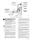
IMPORTANT: To ease CV-2 electrical connections, re-
move weld output terminal mounting bracket from left
front upright Also, before securing CV-2 panel after in-
stallation, check for clearance between lugs of
preinstalled cables on the AC/DC Selector switch termi-
nals and any welding generator components. Reposi-
tion lugs at switch terminals as necessary to prevent
contact between parts.
2. Install and secure the supplied CV-2 panel onto
the welding generator with the hardware re-
moved in Step 7 of Section A.
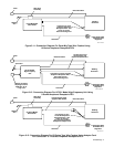
C. Electrical Connections
1. Disconnect cable 30 from rear of Negative weld
output terminal.
2. Install a 6 in. (152 mm) long piece of supplied in-
sulated tubing onto cable 30 disconnected in
Step 1.
IMPORTANT: If unit is equipped with dc meters, con-
nect negative (black) voltmeter lead at the connection
point where cables 30 join together. Be sure that the
voltmeter lead is installed last on top of the two cable ter-
minal lugs.
3. Reconnect cable 30 to switch S1 cable 30 and se-
cure with a supplied 1/4-20 x 1/2 in. flange screw
and nut (see Figure 3-2).
4. Slide the installed tubing over connections, and
secure with two supplied nylon cable ties (see
Figure 3-2).
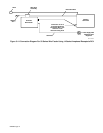
5. Disconnect cable 19 from rear of Positive weld
output terminal.
6. Install the remaining 6 in. (152 mm) long piece of
insulated tubing onto cable 19 disconnected in
Step 5.
7. Reconnect cable 19 to switch S1 cable 19, and
secure with a supplied 1/4-20 x 1/2 in. flange
screw and nut (see Figure 3-2).
8. Slide the installed tubing over connection, and
secure with two supplied nylon cable ties (see
Figure 3-2).
9. Connect cable 28 from switch S1 to rear of Nega-
tive weld output terminal (see Figure 3-2).