


OM-880 Page 8
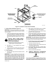
SB-112 332-A
LEFT
FRONT
Welding
Generator Frame
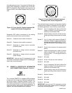
Big 40 Diesel, Big 40G, And
Big 50 Diesel Transformer
Mounting Bracket
Transformer
T2
RIGHT
Use Switch Guard
As Template To
Mark Hole Locations
Switch Guard
(Angle Bracket)
Install Switch Guard Onto
Lower Front Portion Of
Base Just Below New
Lower Front Panel
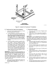
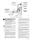
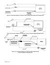
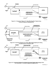
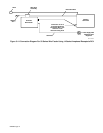
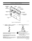
Figure 3-5. Location For Switch Guard Installation
D. Switch Guard Installation (Figure 3-5)
IMPORTANT: Switch guard installation is only neces-
sary on welding generators without this bracket installed
from the factory.
1. Locate the supplied switch guard (angle bracket),
and using the guard as a template, mark the two
mounting hole locations onto lower front portion
of the welding generator base as shown in Figure
3-5.
CAUTION: METAL FILINGS AND/OR
TOOL CONTACT WITH INTERNAL COM-
PONENTS can damage unit.
• Cover internal components.
• Clean unit, and remove internal covering
material before resuming operation.
2. Drill 9/32 in. (7 mm) diameter hole at each
marked location.
3. Install and secure the switch guard with the two
supplied 5/16-18 x 3/4 in. self-forming screws.
E. Final Procedure
1. Reinstall weld output terminal bracket onto left
front upright.
IMPORTANT: To ease reinstalling of the weld output
terminal bracket, position cables 19 and 30 below the
bottom edge of the bracket so that the cables are routed
along the left side of the stator barrel. Also, check the
bimetal jumper bar connection at the rear of the weld
output terminal after reinstalling the bracket; tighten the
bimetal jumper bar securing hardware if necessary.
2. Affix supplied ELECTRODE label over NEGA-
TIVE designation for weld output terminal.
3. Affix supplied WORK label over POSITIVE des-
ignation for weld output terminal.
4. Connect weld cables to weld output terminals as
follows: Electrode holder cable to weld output
terminal labeled ELECTRODE, and work clamp
cable to weld output terminal labeled WORK.
IMPORTANT: Once weld cables are connected to the
unit, the Selector Switch position provides the desired
DC polarity or AC to the weld output terminals.
5. On all welding generator models except BIG 30A
DIESEL, reinstall components as follows:
a. Reinstall and secure top cover.
b. Reinstall and secure the air cleaner hose onto
the engine intake manifold.
6. On BIG 40 DIESEL, BIG 40G, and BIG 50 DIE-
SEL models: Reinstall and secure the muffler
onto the exhaust pipe.
7. Close and secure both side doors.
3-2. REMOTE-5 RECEPTACLE INFORMATION
AND CONNECTIONS (Figure 3-6 And 4-1)
REMOTE-5
The 5-socket REMOTE-5 receptacle RC3 provides a
junction point for connecting a Remote Contactor and/or
Amperage or Voltage Control to the control circuitry of