


– 13 –
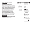
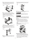
5. Bag “C” - Join the right frame leg and the left frame
leg by using the rear top / bottom leg support (8, 9),
six square neck bolts (10) and six nuts (11).
Fig. C
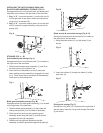
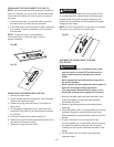
6. Bag “F” - Place three foot pads (13) onto the legs
(3, 5, 6), thread the adjustable foot pad with hex nut
(14) into the front right leg (2).
7. Place stand on level surface and adjust, so all legs
are contacting the floor and are at similar angles to
the floor and detents in stand leg align with supports,
then tighten all bolts.
NOTE: Stand should not rock after all bolts are
tightened.
Fig. D
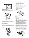
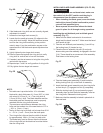
8. Bag “H” - Install the front casters (15) and rear
casters (16) to the bottom of the caster bracket (17).
NOTE: Identify the front casters and rear casters
before installing.
Fig. E
Estimated Assembly Time: 90~120 minutes
(2 people)
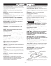
For your safety, never connect plug to power source
receptacle until all assembly and adjustment steps
are complete, and you have read and understood
the safety instructions.
ASSEMBLING STAND (FIG. A~I)
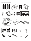
1. Unpack all parts and group by type and size. Refer
to parts list for quantities. The number is labeled
on each leg and leg support, please identify before
assembling.
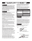
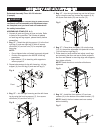
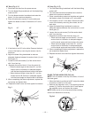
2. Bag “C” - Attach the right leg support (1) to the front
right leg (2) and rear right leg (3) with six square
neck bolts (10) and six nuts (11) to complete right
frame leg.
NOTE:
• Do not tighten bolts until stand is properly aligned.
• Position all supports to the INSIDE of the leg
assembles.
• Align detents (12) in stand leg with supports to
ensure proper fit.
3. Repeat above steps for the left frame leg - left leg
support (4), front left leg (5) and rear left leg (6).
Fig. A
4. Bag “C” - Join the right frame leg and the left frame
leg by using the front leg support (7), four square
neck bolts (10) and four nuts (11).
Fig. B
Front
ASSEMBLY AND ADJUSTMENTS
2
12
1
11
10
3
11
10
7
Front
10
11
9
8
Front
16
17
15
WARNING
!
13
14
Front
2
3
5
6
6
4
5