


– 16 –
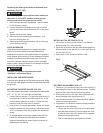
Fig. P
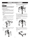
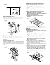
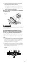
Miter gauge storage (Fig. Q)
Storage for miter guage (1) is located on the right side
of the stand. Hang the miter gauge on the hook (2).
Fig. Q
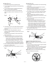
Rip fence storage (Fig. R)
Storage brackets for the rip fence (1) is located on the
left side of the stand. Place the rip fence on the two
hooks (2).
Power cord storage (Fig. R)
Storage for the power cord (3) is located on the left side
of the stand. Wrap the power cord onto the brackets (4)
when saw in not in use. This can prevent damage to the
cord.
Fig. R
2
1
2
1
2
1
3
4
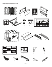
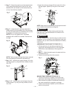
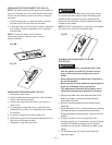
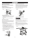
ASSEMBLING THE TABLE EXTENSION (FIG. S)
1. Place the left table extension next to the saw
table, aligning the mounting holes (1).
2. Bag “Q” - Place three bolts with washers (2) and
thread in mounting holes.
3. Place a straight edge or combination square on
the saw table, across the table extension.
4. Adjust the mounting bolts (2) until the extension
is flush with the saw table, and tighten.
NOTE: Extensions will not be flush on outer edges at
this time until rails are installed.
5. Repeat these procedures for the right table
extension.
Fig. S
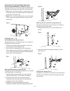
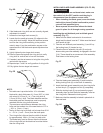
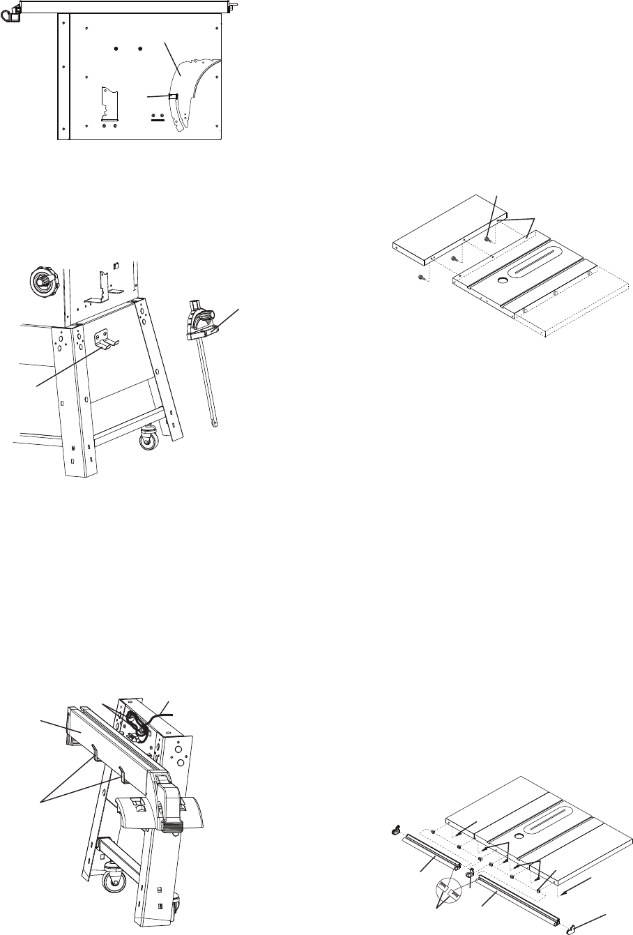
ASSEMBLING THE FRONT AND REAR TABLE RAIL
(FIG. T, U)
Assembly the front rail (Fig. T)
1. Identify the right front rail (1) and the left front rail (2)
by rail scales (3).
2. Bag “R” - Attach the right front side cover (4) into
right front table rail (1). Repeat for the left front rail.
3. Bag “S” - Place four long hex bolts (5), two short hex
bolts (6) through the holes at the front table edge.
Screw the square nuts (7) onto each bolts.
NOTE: Keep the bolts and square nuts loosened
before attaching front rail.
4. Attach the right front rail onto proper location by
having the square nuts pass through the slot of the
front rail. Repeat for the left front rail.
5. Attach the middle plug (8) to connect the two front rail
halves.
6. With the blade installed, use the rip fence and gauge
to adjust the front rail to proper location. When the
front rail is level with table, then fix the front rail by
tightening the six bolts. NOTE: Place straight edge
across table and extension and lift rail until edge is
flush, then tighten bolts. Repeat for other side.
Fig. T
2
1
0
1
0
1
2
1
3
5
5
7
6
6
4
8