


– 21 –
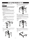
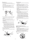
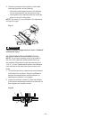
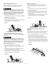
Removing the blade guard and anti-kickback pawl
assembly (Fig. FF, GG)
To avoid injury from an accidental start, make sure
the switch is in the OFF position and the plug is
disconnected from the power source outlet.
1. With the blade elevation handwheel raise the blade
to the maximum height.
2. Loosen the blade lock handle do not pull on handle
just turn and move the handwheel to 90° on the bevel
scale.
3. Tighten the bevel lock handle.
4. Remove the anti-kickback pawl assembly (1) by
lifting the locking lever (2).
5. Remove the blade guard assembly (5) by pulling up
on the locking knob (4).
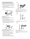
AVOID KICKBACKS
(Work thrown back towards you) by keeping the blade
sharp, the rip fence parallel to the saw blade and by
keeping the riving knife, anti-kickback pawls and guards in
place, aligned and functioning. Do not release work before
passing it completely beyond the saw blade. Do not rip
work that is twisted, warped or does not have a straight
edge to guide it along the fence. Do not attempt to reverse
out of a cut with the blade running.
Improper riving knife alignment can cause
“kickback” and serious injury.
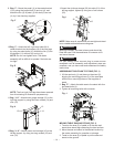
INSTALLING THE MITER GAUGE
Insert the miter gauge bar into the table top grooves.
Make
sure that the miter gauge bar slides freely through the table
top grooves.
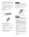
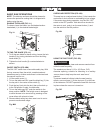
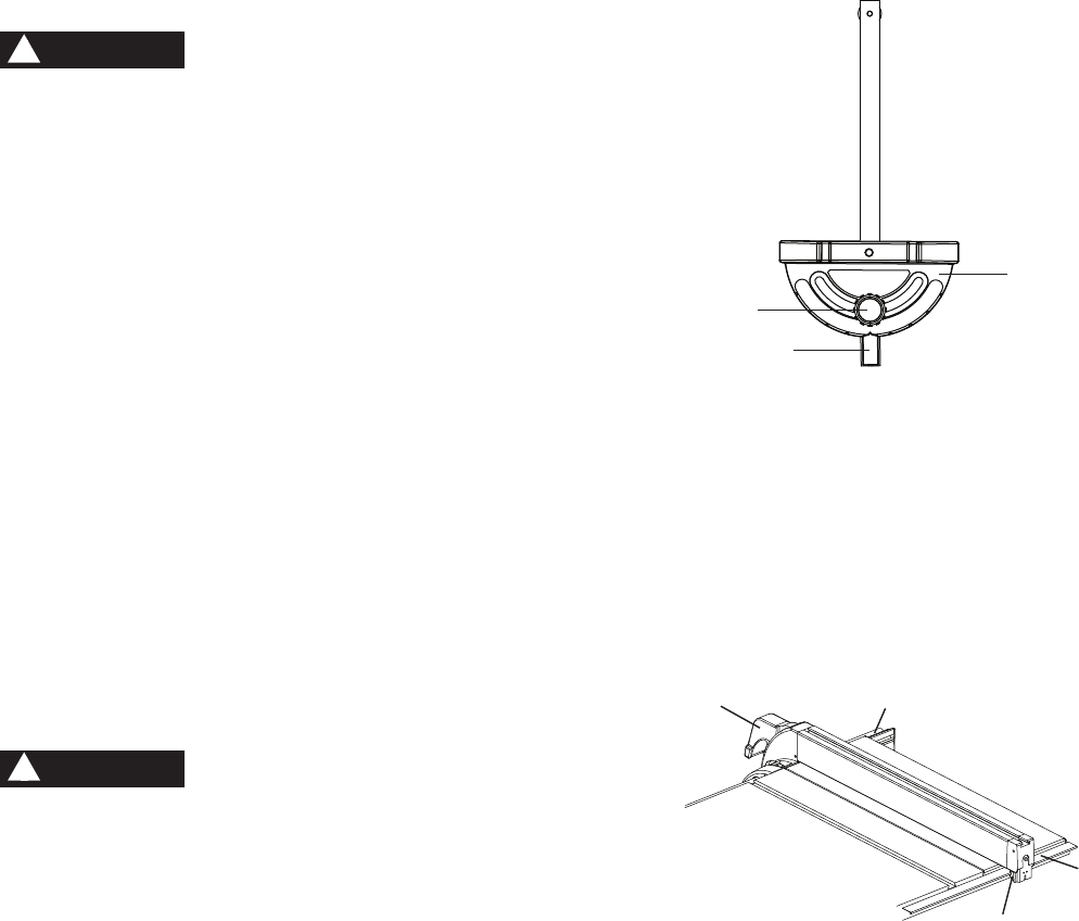
ADJUSTING THE MITER GAUGE (FIG. HH)
The miter gauge is accurately constructed with index stops
at 0
°, 15°, 30°, 45°, 60° both right and left sides.
1. Loosen the lock handle (1) to allow the miter body (2)
to rotate freely. Position the miter body at 90° so the
positive detent secures its position. Tighten the lock
handle to hold the miter body in position.
2. If the pointer (3) requires adjustment, loosen the screw
under the pointer with a screwdriver. Adjust the pointer
to 90° on the scale, then firmly tighten the adjustment
screw.
3. To change angles on the miter gauge, loosen the lock
handle (1) and rotate the miter body to the desired
angle as indicated by the scale. Secure in position by
tightening the lock handle.
WARNING
!
WARNING
!
Fig. HH
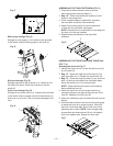
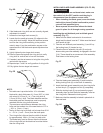
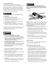
INSTALLING THE RIP FENCE (FIG. II)
1. Lift upward on the rip fence handle (1) so the rear
holding clamp (2) is fully extended.
2. Place the rip fence on the saw table and engage the
holding clamp to the rear rail (3). Lower the front end
into the front rail (4).
3. Push down on the rip fence handle to lock.
Fig. II
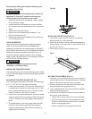
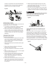
RIP FENCE ADJUSTMENT (FIG. JJ)
1. The fence (1) is moved by lifting up on the handle (2)
and sliding the fence to the desired location. Pushing
down on the handle locks the fence in position.
2. Position the fence on the right side of the table and
along the edge miter gauge groove (3).
3. Lock the fence handle. The fence should be parallel
with the miter gauge groove.
4. If adjustment is needed to make the fence parallel to
the groove, do the following:
• Loosen the two bolts (4) and lift up on the handle.
• Hold the fence bracket (5) firmly against the front
of the saw table. Move the fence until it is parallel
with the miter gauge groove.
• Push the handle down and tighten both bolts.
1
2
3
2
1
4
3