


– 18 –
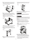
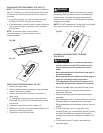
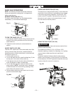
90° Stop (Fig. X, Y)
1. Disconnect the saw from the power source.
2. Turn the blade tilting handwheel until the blade tilting
scale is at 90°.
3. Turn the blade elevation handwheel and raise the
blade (1) to the maximum elevation.
4. Place a combination square (2) on the table and
against the blade to check if the blade is 90° to the
table.
Fig. X
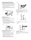
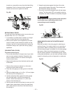
5. If the blade is not 90° to the table. Remove the back
cover of the base by removing the screws, two for
each side.
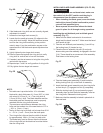
6. Adjust the blade tilting handwheel to make an
adequate distance between the anchor block (1) and
bevel gear (2).
7. Loosen the two set screws (3) of the anchor block
with 3 mm hex key.
8. Separate the anchor block (1) from the worm (4).
• When the bevel angle is more than 90°, turn the
anchor block to A direction in adequate degree
until the bevel angle and bevel scale is the same.
• When the bevel angle is less than 90°, turn the
anchor block to B direction in adequate degree
until the bevel angle and bevel scale is the same.
9. When completing the above adjustment, replace the
set screws and tighten them.
10. Replace the back cover and then tighten the screws.
Fig. Y
A
B
2
1 3 4
1
2
90° 45°
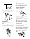
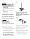
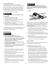
45º Stop (Fig. X, Z)
1. Turn the blade tilting handwheel until the blade tilting
scale is 45°.
2. Turn the blade elevation handwheel and raise the
blade to the maximum elevation.
3. Place a combination square on the table and against
the blade to check if the blade is 45° to the table.
4. If the blade is not 45° to the table. Remove the back
cover of the base by removing the screws, two for
each side.
5. Adjust the blade tilting handwheel to make an
adequate distance between the anchor block (1) and
bevel gear (2).
6. Loosen the two set screws (3) of the anchor block
with 3 mm hex key.
7. Separate the anchor block from the worm (4).
• When the bevel angle is more than 45°, turn the
anchor block to A direction in adequate degree
until the bevel angle and bevel scale is the same.
• When the bevel angle is less than 45°, turn the
anchor block to B direction in adequate degree
until the bevel angle and bevel scale is the same.
8. When completing the above adjustment, replace the
set screws and tighten them.
9. Replace the back cover and then tighten the screws.
Fig. Z
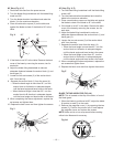
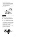
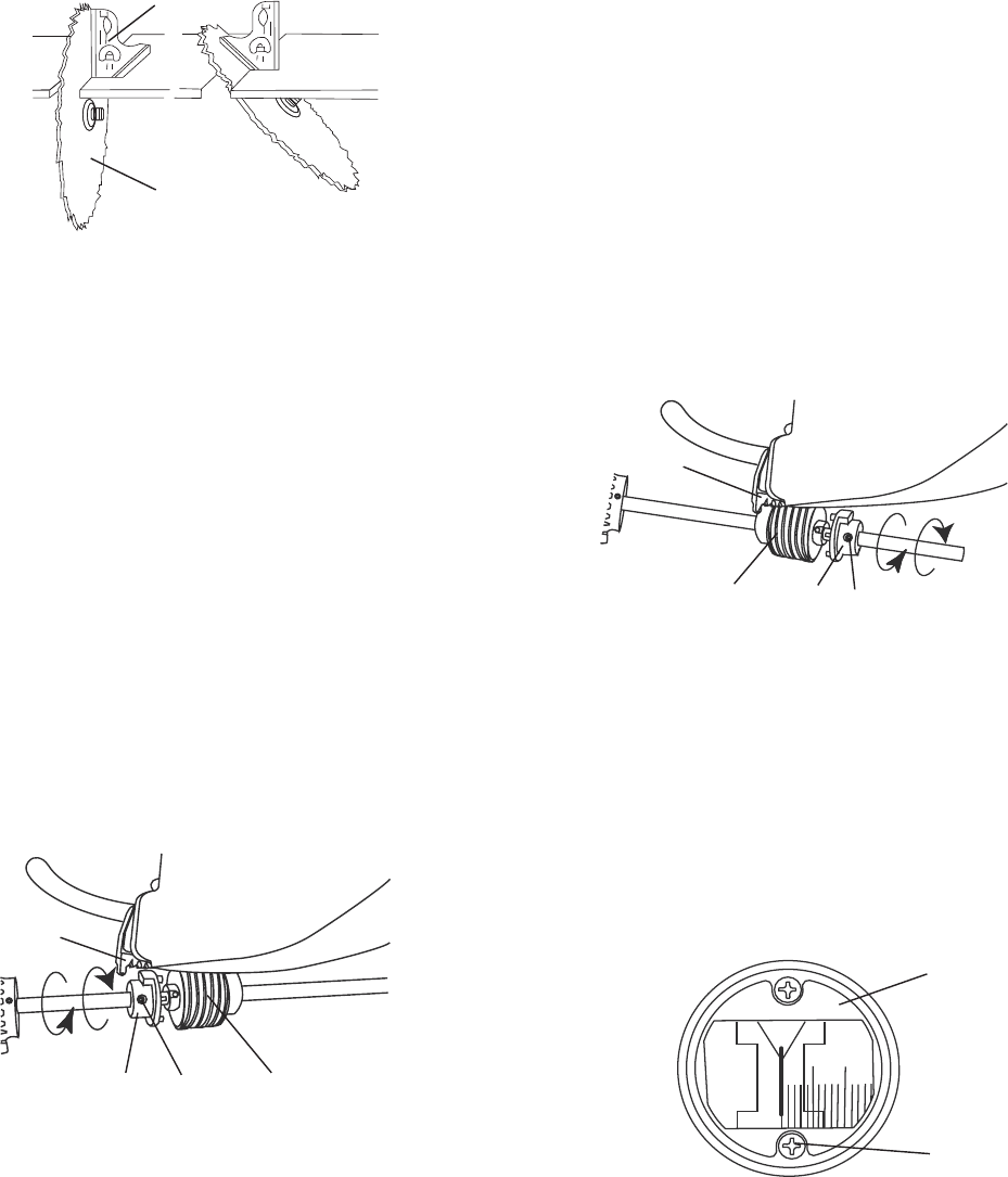
BLADE TILTING INDICATOR (FIG. AA)
NOTE: This is located on the top of the table, in front of
the blade guard
1. When the blade is positioned at 90º, adjust the blade
tilt pointer to read 0º on the scale.
2. Remove the magnifier cover (1) by removing the two
screws (2). Position the pointer over 0º and replace
the magnifier cover and replace the screws
NOTE: Make a trial cut on scrap wood before making
critical cuts. Measure for accuracy.
Fig. AA
B
A
4
2
1
3
0
5
10
2
1