


– 15 –
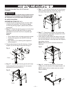
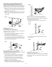
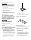
INSTALLING THE ANTI-KICKBACK PAWL AND
BLADE GUARD ASSEMBLY STORAGE (FIG. K)
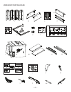
Storage brackets for anti-kickback pawl and blade guard
assembly are located on the right side of the saw base.
1. Bag “J, K” - Insert the bracket (1) into the left slot (2)
on the right side of saw base, attach the brackets by
using two of six screws (22).
2. Bag “J, K” - Insert the support plate (4) into the right
slot (5), attach the support plate by using two od six
screws (22).
Fig. K
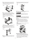
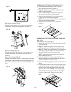
STORAGE (FIG. L ~ R)
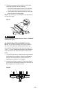
Anti-kickback pawl storage (Fig. L)
Storage brackets for anti-kickback pawl (1) is located on
the right side of the saw base.
1. Take the anti-kickback pawl assembly (1) and lift up
the locking lever (2) located on top.
2. Place the front of assembly into slot (3) and push
down making sure the assembly is engaged in the slot
(3, 4). There should be no movement of the assembly.
Push down on the locking lever.
Fig. L
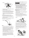
Blade guard assembly storage (Fig. M)
Storage brackets for blade guard assembly (1) is located
on the right side of the saw base.
1. Take the blade guard assembly (1) and locate the
sliding locking knob (2) on the back of assembly.
2. Slide the locking knob up and press the guard
assembly down along the step (3) so that the ball
engages into hole (4) completely.
3. Release the locking knob. Make sure that the
assembly is locked in place and supported by plate (5).
Fig. M
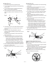
Blade wrench & push stick storage (Fig. N, O)
Storage for blade wrench and push stick is located on
the right side of the saw base.
1. Hang the blade wrench (1) on the holder (2) as
shown.
Fig. N
2. Insert the holders (2) through the holes (3) of the
push stick (4).
Fig. O
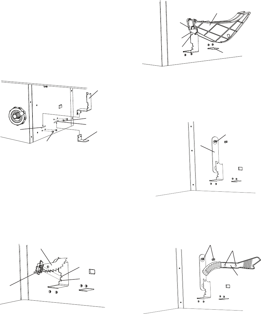
Riving knife storage (Fig. P)
Storage for riving knife (1) is located on the right side of
the saw base. Insert the riving knife through the holder
(2) as shown.
1
4
22
5
2
22
3
4
1
2
1
2
2
3
4
1
4
2
3
5