


10
permanent wiring system; or to a system having an
equipment-grounding conductor.
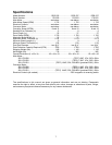
Make sure the voltage of your power supply
matches the specifications on the motor plate of
the machine
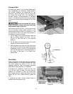
Abrasive Paper Installation
Disconnect machine from
power source.
Proper attachment of the abrasive strips to the
drums is important for achieving top performance
from the sander.
See page 38 for a list of available abrasive strips
with their respective grits and some tips on
choosing the proper strip for a particular job. If
using different size grits simultaneously, always
place the coarser grit on the front drum.
Attach the abrasive paper as follows:
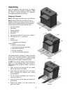
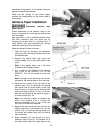
1. Open the hood by removing the handwheel
and turning the two locking handles at the front
counterclockwise.
2. Remove the socket head cap screw and
locking wedge (Fig. 8) from both ends of the
drum.
Note: If the wedge sticks, use a flat head
screwdriver as leverage to free it.
3. Cut a length of the Ready-To-Cut abrasive
strip (14'-9" for the DDS-225, 21'-3" for the
DDS-237). This will be enough to cover one
drum.
Note: The taper on the remaining roll can later
be used for the starting edge of your next strip.
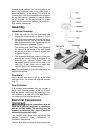
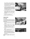
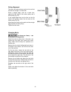
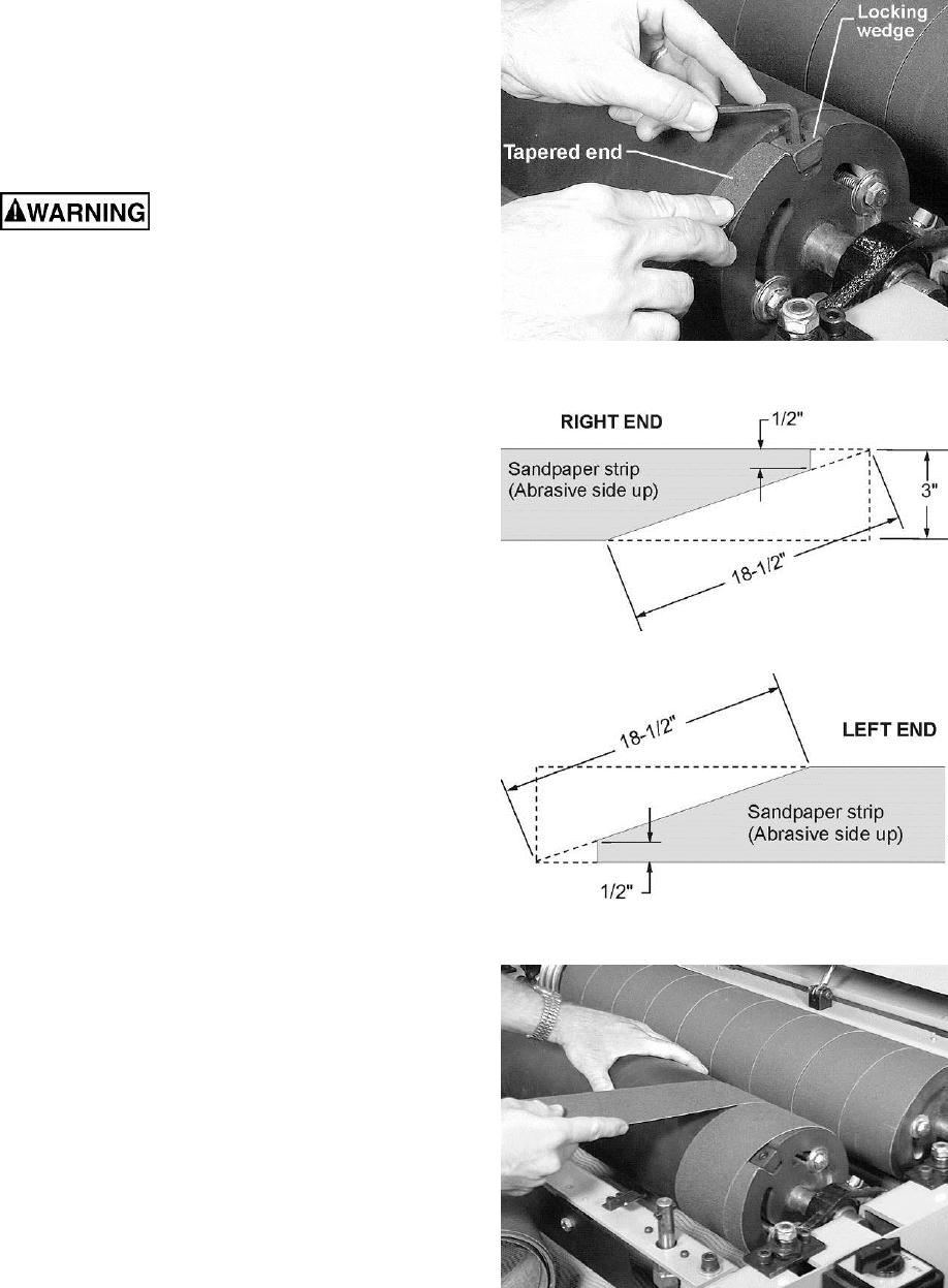
4. Mark and cut a taper at the right end of the
abrasive strip (Fig. 9). Because the tapered
end should use all of the recess at the right
side of the drum, its end must be trimmed back
leaving an edge of about 1/2 inch, as shown.
Now trim the left side of the abrasive paper in
a similar manner (Fig. 10).
Note: An alternate method of tapering the
ends of the abrasive strip is to place the
removed sandpaper strip on top of the new
strip and to use this as a template.
5. Begin at the right end of the drum and tuck the
tapered right end of the abrasive roll into the
recess (Fig. 8). Place the locking wedge into
the recess and tighten firmly with the socket
head cap screw.
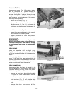
6. Begin wrapping the strip around the drum,
keeping it taut as you go. The tapered cut of
the strip should follow the right edge of the
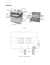
Figure 8
Figure 9
Figure 10
Figure 11