


11
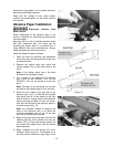
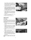
drum. Continue to wrap the abrasive in a
clockwise spiral fashion by rotating the drum
with your left hand and guiding the strip with
your right hand (Fig. 11). Successive windings
of the strip should be flush with previous
windings without any overlap.
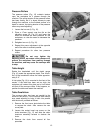
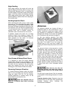
7. The left end of the drum which contains the
recess is an independent piece (Fig. 12) that
can be rotated on the drum. This fastener is
spring-tensioned to take up any slack and hold
the abrasive strip firmly to the drum. Rotate
this fastener backward and hold it there with
your thumb as shown in Fig. 12.
8. Tuck the tapered left end of the strip into the
recess, as shown in Fig. 12, then insert the
locking wedge and socket head cap screw,
tightening the screw until the locking wedge is
firmly seated.
9. Release the spring-tensioned fastener. The
abrasive strip is now ready for use.
10. Repeat this procedure for the other drum.
Adjustments
Drum Height
When using different abrasive grits on the drums,
the height of the drums from the workpiece must
vary. To achieve this, the back drum (which should
always have the finer grit) has been designed for
easy adjustment.
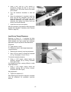
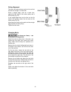
1. Loosen the locking levers (Fig. 13) on both
sides of the machine by rotating them counter-
clockwise.
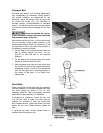
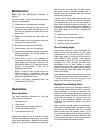
2. Rotate the adjustment knob to the desired
measurement, using the red triangular
indicator at the base of the dial. A label is
affixed below the locking lever showing the
proper settings. It is also shown in Fig. 14.
3. Repeat this dial setting on the opposite end of
the drum.
Note: It is important that the dial setting be
identical at both ends of the drum.
4. Tighten the locking levers (Fig. 13) by rotating
clockwise, before operating the sander.
Note: The locking levers are spring loaded –
you can move the handle to any position by
pulling out on the lever, rotating it on the hub,
then releasing.
Important: After changing abrasive strips, always
check and, if necessary, reset the back drum
height.
Figure 12
Figure 13
Figure 14