


18
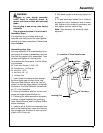
This concludes the assembly section. Except for installing table boards, fence, and table clamps
the saw should be completely assembled. The next section deals with adjusting your saw to
remove any "looseness" in order to get accurate cuts.
Assembly
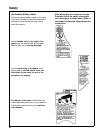
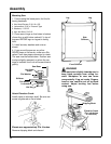
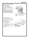
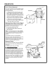
Remove saw blade.
1. Tighten carriage lock knob, located on
rightsideofarm.
2. Loosen guard clamp screw approximately
4 turns. Rotate dust elbow so opening is fac-
ing left.
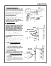
3. Use one hand to lift the clear plastic
guard at the front of the saw.
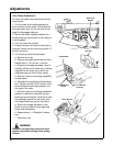
4. Use the other hand to grasp the rear of
the guard (below the dust elbow).
5. Rotate the entire guard assembly forward
approximately 45°.
6. Remove the guard assembly.
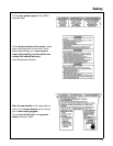
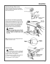
7. Motor shaft has left hand threads. Hold
shaft wrench and rotate arbor wrench down
(clockwise).
8. Remove shaft nut, outer collar, saw
blade, and inner collar. Set aside and out of
the way.
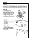
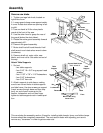
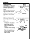
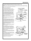
Attach Table Supports
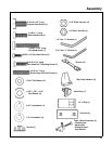
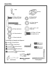
1. Set out:
- two table supports
- four 5/16" 18 x 3/4" long square head
screws
- four 11/32" x 7/8" x 1/16" flatwashers
-four5/16"lockwashers
- four 5/16" hex nuts
2. Attach supports to side frame, making
sure to use correct holes in table supports
and side frame: Use two screws per support
(insert screws through base and then sup-
port); on end of each screw put a flat
washer, lockwasher and nut then finger
tighten so table supports rest in lowest posi-
tion.
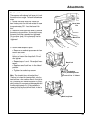
Pull down
to loosen
Blade
Rotation
Table
Support
Screws
Here
Nut
Lockwasher
Flatwasher
Front
Base
Square Head Screw
5/16 - 18 x 3/4"
Mount rails using
these holes
Table
Support