


21
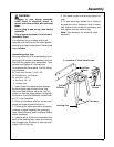
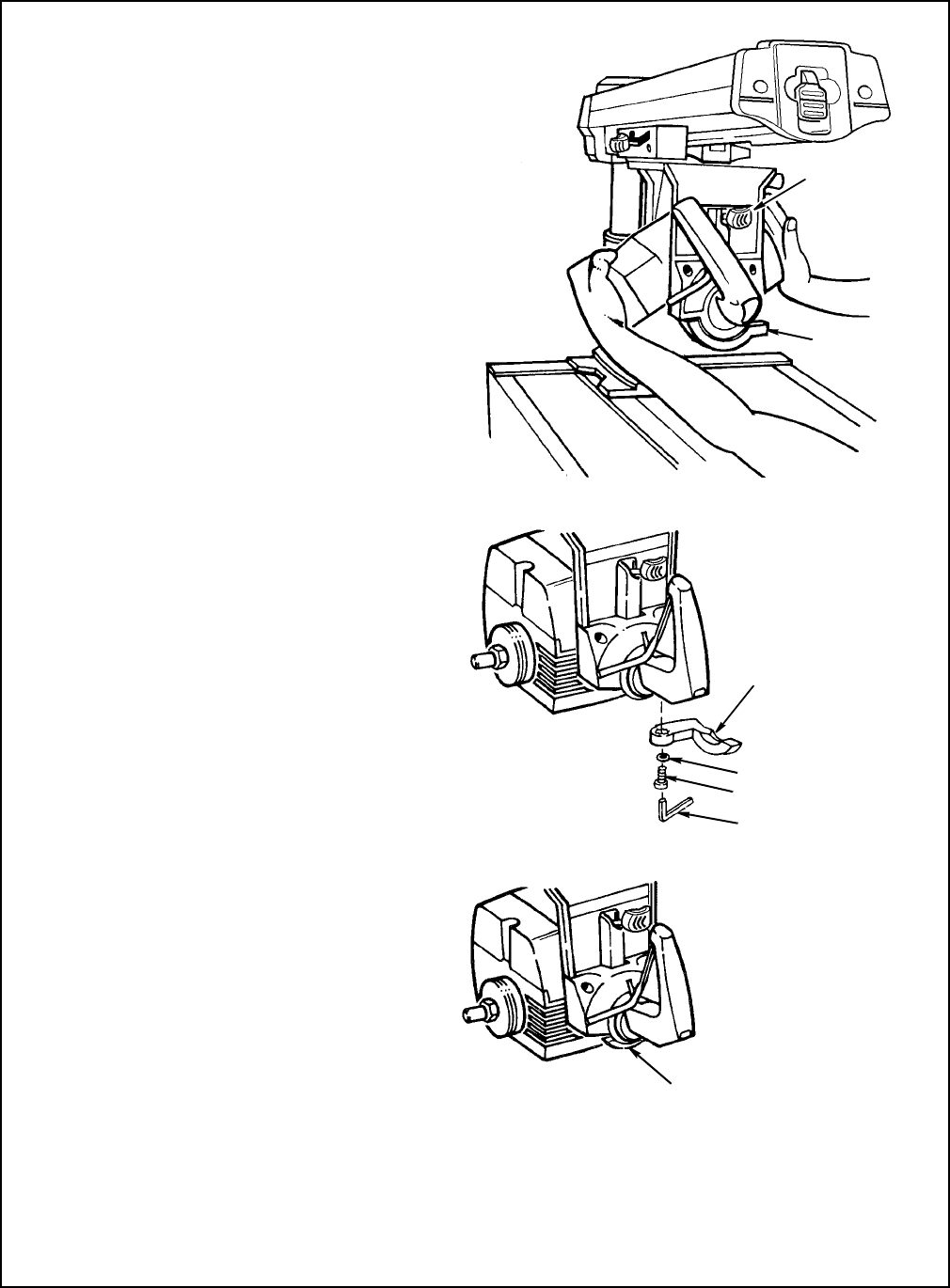
Bevel Lock Lever
The purpose of the bevel lock lever is to lock
the motor at any angle. To check follow these
steps:
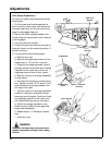
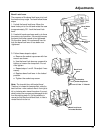
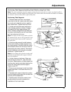
1. Unlock the bevel lock lever. Move the
bevel index pin to the left and rotate the saw
to approximately 30°. Lock the bevel lock
lever.
2. Use both hands as shown and try to force
the motor out of position. If the motor moves,
the bevel lock lever needs to be tightened.
On the other hand if it is extremely hard to
lock the bevel lock lever it has been over
-tightened.
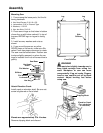
3. Follow these steps to adjust:
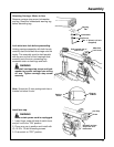
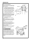
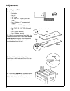
a. Remove the socket cap screw with hex
wrench as shown.
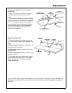
b. Use the bevel lock lever as a wrench to
tighten or loosen the clamp bolt. Do not
over tighten.
c. Repeat steps 1 and 2. Re-adjust if nec-
essary.
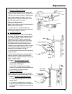
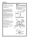
d. Replace bevel lock lever in the locked
position.
e. Tighten the socket cap screw.
Note:
The clamp bolt has a left handed thread.
Therefore, to increase the clamping effect, rotate the
bevel lock lever - when used as a wrench -from right to
left, or clockwise when viewed from above. If you acci-
dentally rotate it the wrong way and disengage the bolt
from the matching steel nut, it will be necessary to
remove the Yoke Handle, and Bevel Scale, in order to
reinstall the bolt into the nut.
Bevel Index
Pin
Bevel Lock
Lever
Bevel Lock
Lever
Lockwasher
Socket Cap Screw
1/8" Hex “L” Wrench
Bevel Lock Lever
In Locked Position
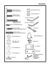
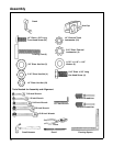
Adjustments