


23
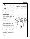
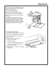
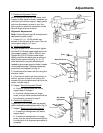
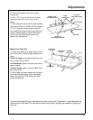
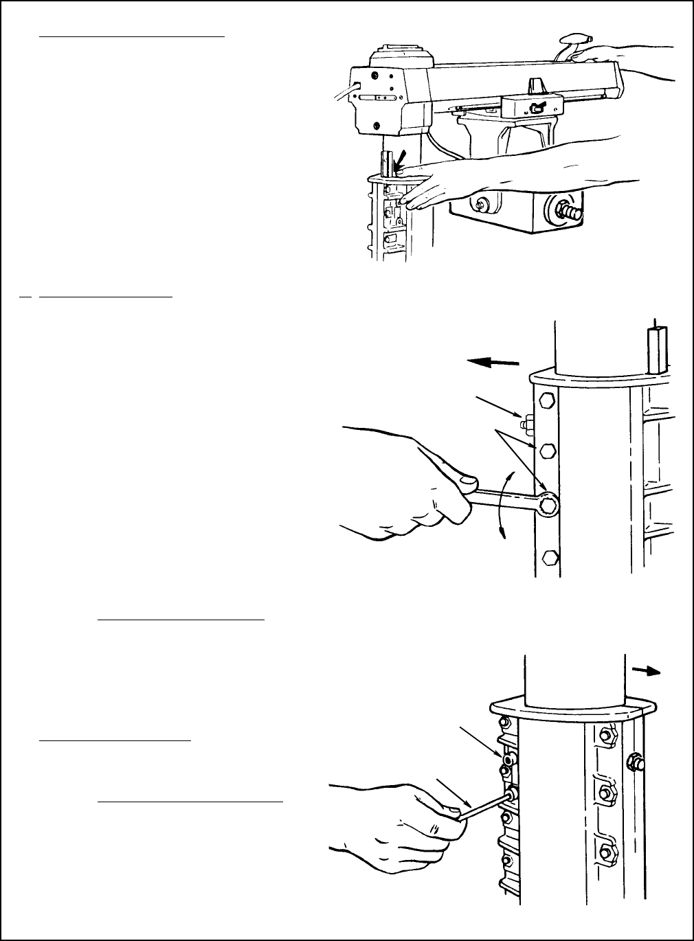
3. Rotational Alignment Check:
While holding the arm with one hand, hold
fingers of other hand as shown, between col-
umn tube and column support. Apply gentle
side-to-side pressure at end of arm. Any
side-to-side or rotational movement can be
felt with finger at arrow location.
Alignment Adjustments
Note:
If Vertical Alignment was OK and adjustment is
not
needed, proceed to step 6.
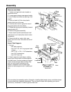
1. Loosen (2) 1/4 - 20 Gib socket cap
screws on the left side at the rear of the col-
umn support slightly (1/2 turn).
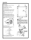
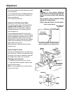
2.
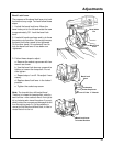
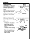
Vertical Adjustment:
Using the closed end of a box wrench, tighten
all of the 5/16-18 black screw heads on the col-
umn support casting 1/16th to 1/8th of a turn.
Tighten the (2) 5/16-18 silver screw heads
slightly more than the black ones to achieve a
close fit to the column tube (Fig. 2). (A 1/4"
drive ratchet with a six point socket may be
needed to get enough torque on bolts.) Loosen
nut on brass set screw. Tighten the brass set
screw firmly and retighten nut (Fig. 2).
3. Elevate and then lower the Arm using the
elevation crank.
4. If the column tube binds and elevation is
difficult, go back to step 2 and loosen the
screws until you achieve smooth but firm ele-
vation, recheck step 3.
5. Repeat "Vertical Alignment Check
".
a. If vertical misalignment still exists,
repeat steps 2 through 4.
b. If vertical misalignment no longer
exists, and you have achieved smooth but
firm elevation, proceed to step 6.
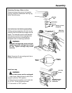
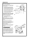
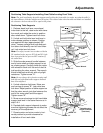
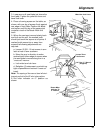
6. Rotational
Adjustment:
Tighten the (2) 1/4-20 Gib socket cap screws
until no noticeable rotational play exists. (Fig. 3).
7. Repeat "Rotational Alignment Check"
a. If rotational misalignment still exists,
repeat step 6.
b. If rotational misalignment no longer
exists, and you have achieved smooth but
firm elevation, this alignment procedure is
complete.
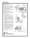
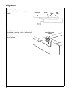
Fig. 1
Front
Bright Plated
Bolts
Tighten
Loosen
Fig. 2
Brass Set Screw
Front
Gib Socket
Capscrews
Hex “L” Wrench
(Supplied)
Fig. 3
Adjustments