


34
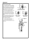
lnstalling and Adjusting Rip Scale Indica-
tors.
Note:
The rip scales and pointers are intended to be
used for quick settings. For greater accuracy, take
direct measurement between blade and fence.
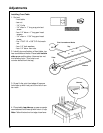
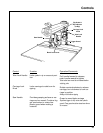
1. Pre-assemble indicator and twin nut.
Loosen but do not remove two screws which
attach left hand carriage cover.
2. Tilt carriage cover and install rip indicator
with twin nut on inside of cover. Tighten car-
riage cover attaching screws.
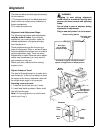
3. Loosen two cover screws. Loosen but do
not remove carriage lock knob in right hand
carriage cover. Install rip indicator. Tighten
carriage cover attaching screws.
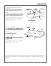
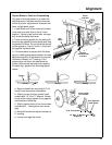
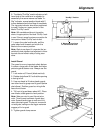
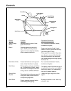
4. With fence in its normal position (next to
front table), loosen yoke lock handle, pull
yoke index lever forward and rotate yoke to
the left to index yoke 90° from the cross cut
position. This will locate saw blade between
motor and fence (“In Rip” position). Lock
yoke lock handle.
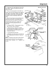
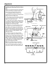
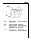
5. Position carriage until edge of blade,
when spun by hand, just touches front face
of fence. The “In-Rip” scale indicator (on the
right hand side of radial arm) should now
read "0" inches on upper portion of the blade
"In-Rip" scale. If not, loosen screws and shift
the indicator until it is aligned with the "0"
mark, then tighten the screws.
Note:
With saw blade and fence in the position
shown, the upper portion of blade "In-Rip" scale is
used. If fence is moved to extreme rear position, the
lower portion of blade "In-Rip "scale would be used.
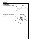
Screw #6-32 x 1/2
Twin Nut
Rip Scale
Indicator
Yoke Index Lever
Yoke Lock Handle
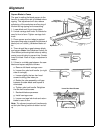
Front
Table
Fence
Rear
Table
Table Spacer Board
In-Rip Position
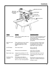
Rip Scale Indicator
Rip
Lock Knob
Alignment