4.2 Wiring the DC bus
NOTICE
EQUIPMENT DAMAGE CAUSED BY INCORRECT POLARITY
Verify correct polarity during installation.
Failure to follow these instructions can result in equipment
damage.
The DC bus is connected by means of a plug and socket connection
or screw terminals.
Cable specifications See chapter "2.4 Cables for the DC bus", page 20 for the cable speci-
fications. Pre-assembled cables and connector kits can be found in
chapter "6 Accessories and spare parts", page 55.
4.2.1 Drives with connectors
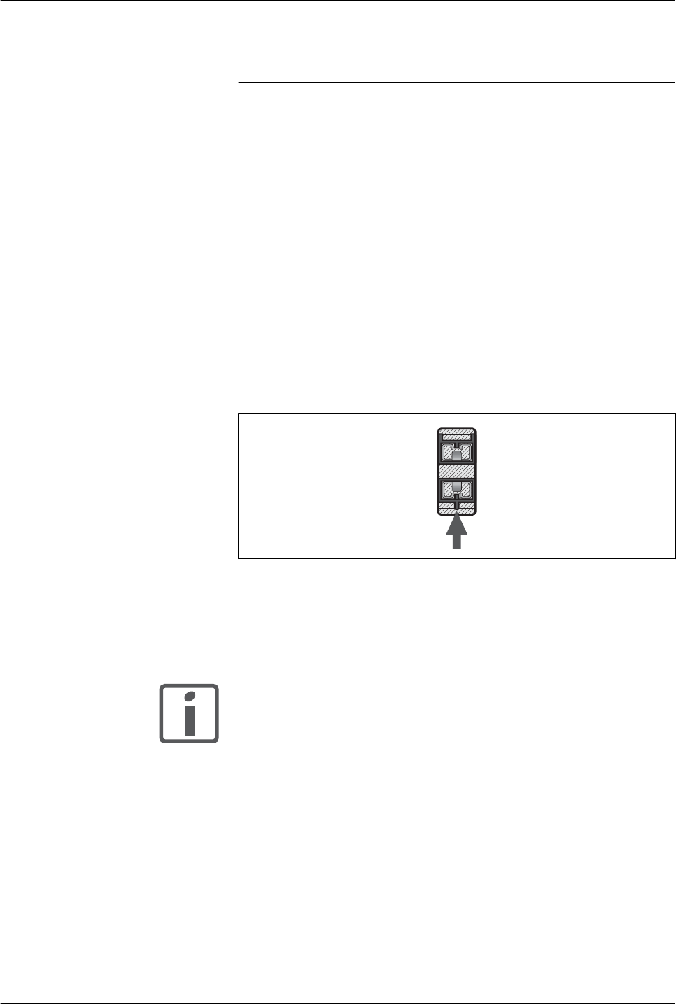
Connector coding The connectors are coded. If you do not use pre-assembled cables,
verify that the crimp contacts properly snap into the connector. Verify
that PA/+ is connected to PA/+ and PC/- is connected to PC/-. Incor-
rect wiring will destroy the devices.
PA/+
PC/-
Figure 15: Connector coding
Connector lock The connector has a snap lock mechanism. Pull the connector hous-
ing to unlock the connector.
Both wires in the connector housing must be able to move independ-
ently for unlocking.
If you want to remove the DC bus connection cable, you must open
the connector lock by pulling at the housing.
The connection cable is easier to remove if you remove the motor
connector first.
LXM32
4 Installation
Common DC bus
45
MNA01M001EN, V1.01, 08.2014


