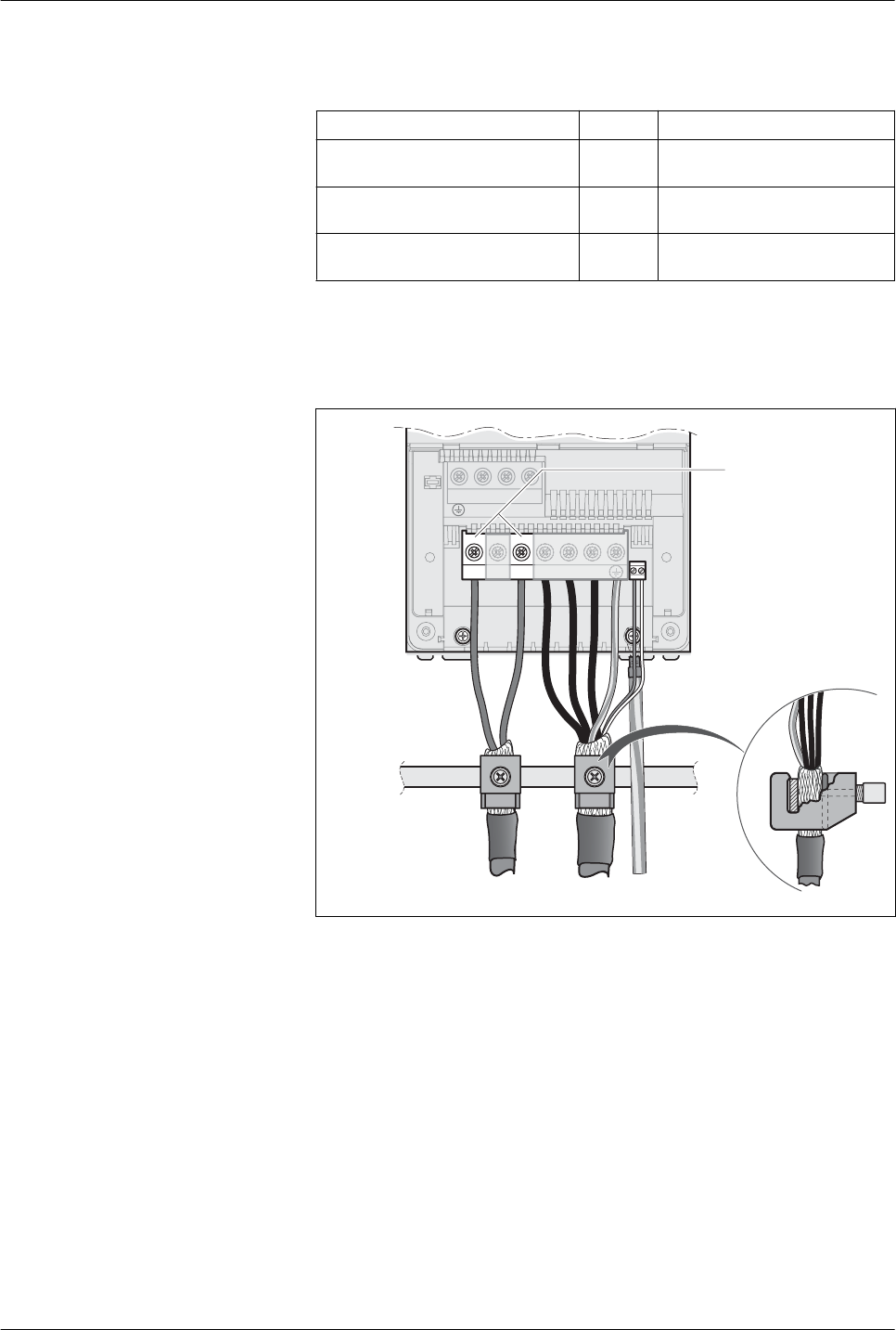
4.2.2 Drives with terminals
This chapter describes LXM32 drives with screw terminals.
Properties of the connection termi-
nals CN9
LXM32∙... D85, C10
Connection cross section mm
2
(AWG)
6 ... 25
(10 ... 4)
Tightening torque for terminal
screws
Nm
(lb.in)
3.8
(33.6)
Stripping length mm
(in)
18
(0.71)
The terminals are approved for fine wire conductors and rigid conduc-
tors. Observe the maximum permissible connection cross section.
Take into account the fact that wire ferrules increase the conductor
cross section.
Wiring diagram
BR+BR-
L3/TL2/SL1/R
CN9
U/T1 W/T3V/T2PA/+ PC/-PB
U
/T
1
W
/T
3
V
/T
2
PB
Figure 18: Wiring diagram DC bus
Connecting the DC bus
▶
Switch off all supply voltages. Observe the safety instructions con-
cerning electrical installation.
▶
Connect the DC bus to the device. Connect PA/+ to PA/+ (red) and
PC/- to PC/- (black). Note the tightening torque specified for the
terminal screws.
▶
Connect the cable shield with a shield clamp to an EMC rail (large
surface area contact).
Verify that the individual wires are in the individual guides.
▶
Mount the cable guide.
LXM32
4 Installation
Common DC bus
47
MNA01M001EN, V1.01, 08.2014


