


DO NOT OPERATE THIS WELDER if the actual power source voltage is less than 100 volts AC or
greater than 125 volts AC. Contact a qualified electrician if this problem exists. Improper performance
and/or damage to the welder will result if operated on inadequate or excessive power.
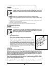
WARNING
ELECTRIC SHOCK CAN KILL! FIRE CAN KILL, INJURE, AND CAUSE PROPERTY DAMAGE!
• To reduce the risk of electric shock and fire, connect only to properly grounded
and fused outlets.
• Never alter the AC power cord provided on the welder. Never alter an extension
cord or extension cord plugs.
EXTENSION CORD USE
For optimum welder performance, an extension cord should not be used unless absolutely necessary.
If necessary, care must be taken in selecting an extension cord appropriate for use with your specific
welder.
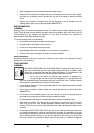
Select a properly grounded extension cord that will mate the AC power cord of the welder with the AC
power source receptacle directly, without the use of adapters. Make sure the extension cord is
properly wired and in good electrical condition.
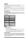
For an extension cord not exceeding 25 feet in length, choose the same AWG wire size as that of the
power cord on the welder. Extension cord lengths longer than 25 feet will require heavier wire gauges
to compensate for voltage losses.
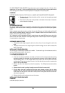
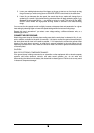
ASSEMBLE HANDLE STRAP
1. Thread the handle strap through the slot in the front of the unit, then through the slot in the
back.
2. Thread the loose end of the strap through the buckle making sure the fabric contacts the
teeth in the buckle.
INSTALLING THE WELDING GUN
The welding gun comes factory-installed to the welder. To remove the gun for maintenance, refer to
maintenance instructions later in this manual.
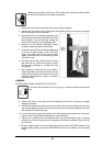
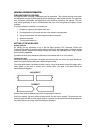
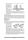
CHANGING THE DRIVE ROLLER
1. Remove drive tension.
2. If there is wire already installed in the welder, roll it back onto the wire spool by hand-turning
the spool clockwise, but be careful not to allow the wire to come out of the tail piece of the gun
without holding onto it, or it will unspool itself. Put the end of the wire into the hole on the
outside edge of the spool and bend it over to hold the wire in place, and then remove the
spool of wire from the welder.
3. Remove the drive roller bracket from the drive assembly. Two Phillips head screws hold the
bracket.
4. Remove the drive roller by pulling it straight out and off of the drive motor shaft.
5. Find the drive roller that is stamped with the same wire diameter as that of the wire being
installed. Push the drive roller onto the drive motor shaft so that the desired groove is to the
inside. Make sure the groove of the roller is lined up with the wire guides and the roller is flush
with the drive assembly.
6. Replace the drive roller bracket and secure the screws.
INSTALLING THE WELDING WIRE
WARNING
ELECTRIC SHOCK CAN KILL!
8