


-18-
For Machines Mfg. Since 8/09
Model SB1027
PREPARATION
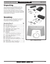
Assembly
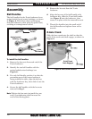
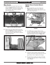
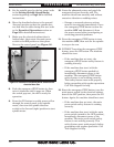
Ball Handles
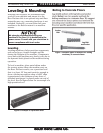
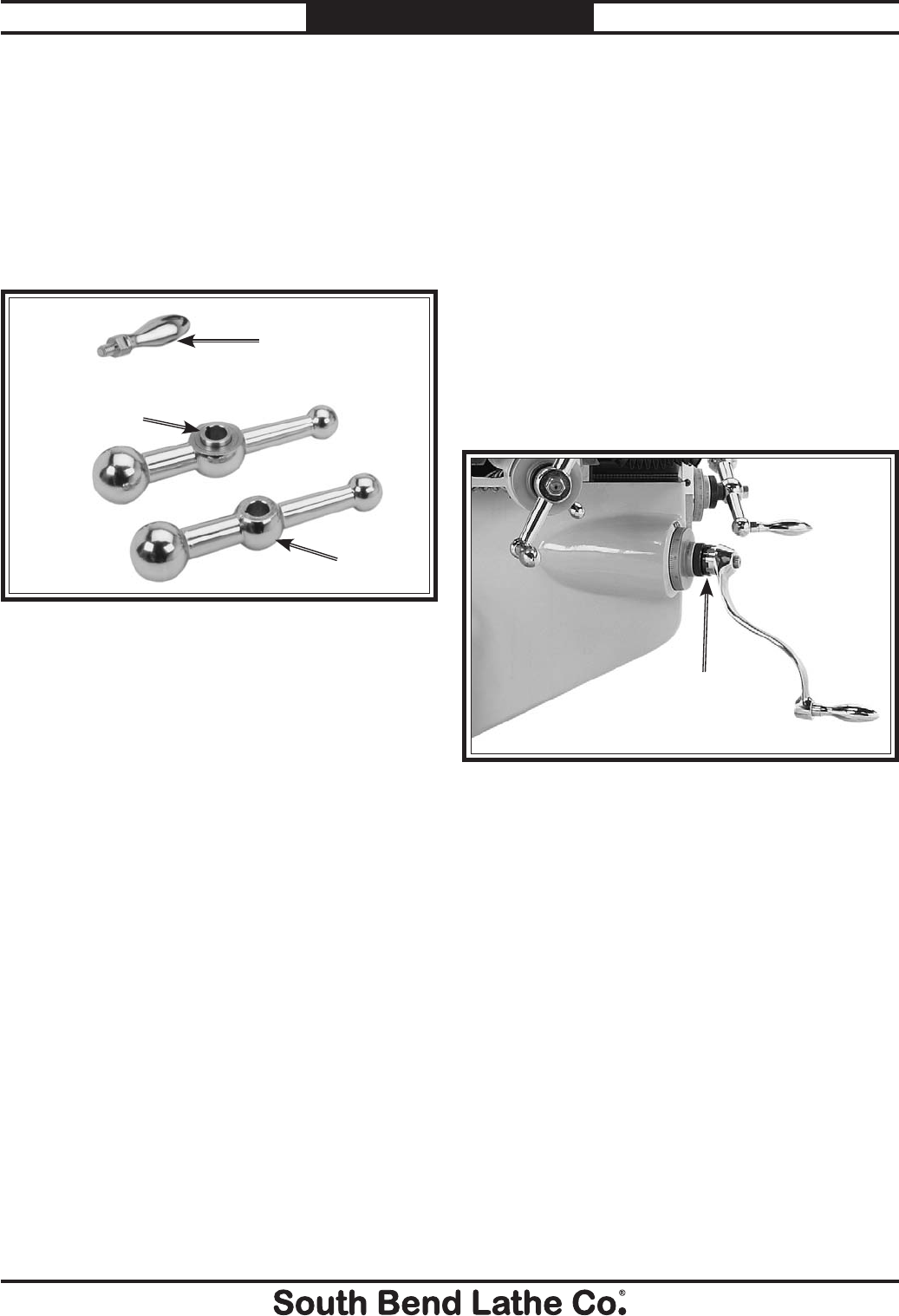
The ball handles for the X-axis leadscrew have
spring-loaded, keyed center bushings, as shown
in Figure 8. This allows them to disengage
from the leadscrew when using the power feed,
avoiding an entanglement hazard.
To install the ball handles:
1. Remove the hex nuts from each end of the
X-axis leadscrew.
2. Identify the two ball handles with the
spring-loaded center bushings (see
Figure 8).
3. For each ball handle, position it so that the
protruding part of the center bushing is
facing toward the table, align the keyway
with the leadscrew key, then slide it onto the
X-axis leadscrew.
4. Secure the ball handles with the hex nuts
removed in Step 1.
Note: Tighten the hex nuts just until they are
snug. Overtightening could increase the
wear of the moving parts.
Figure 8. Ball handle assemblies.
Ball Handle
Handle
Spring-Loaded
Bushing
Y-Axis
Ball Handle
5. Remove the hex nut from the Y-axis
leadscrew.
6. Align the keyway of the ball handle with
leadscrew key, slide the Y-axis ball handle
(see Figure 8) onto the leadscrew, then
secure it in place with the removed hex nut.
7. Thread the handles into the small end of
the ball handles and tighten them with a
wrench.
Z-Axis Crank
Slide the knee crank onto the shaft so that the
teeth of the crank and shaft engage, as shown in
Figure 9.
Figure 9. Z-axis crank installed.
Z-Axis Crank
Teeth Engaged