


For Machines Mfg. Since 8/09 Model SB1027
-19-
PREPARATION
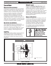
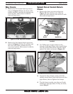
Way Covers
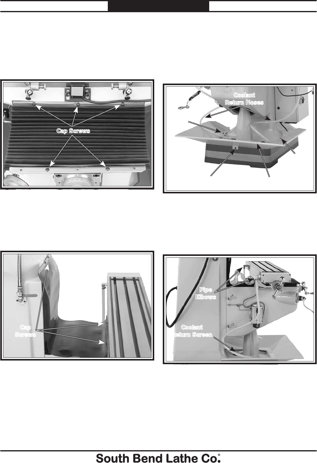
1. Remove the five button-head cap screws
shown in Figure 10 from the front of the
saddle and knee, position the pleated way
cover in place, then secure it with the
removed cap screws.
Figure 10. Front way cover installed.
Cap Screws
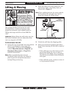
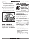
2. Remove the four button-head cap screws
shown in Figure 11 from the column and
the rear of the table, position the rear
way cover in place, then secure it with the
removed cap screws.
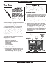
Splash Pan & Coolant Return
Hoses
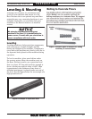
1. Remove the three cap screws shown in
Figure 12 from the base rim, slide the
splash pan into position, then secure it with
the removed cap screws.
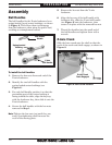
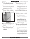
2. Use Teflon tape or pipe sealant on the
threads of the pipe elbows, then install them
into the coolant drain holes located on both
ends of the table, as shown in Figure 13.
Figure 13. Coolant return hose connections.
Pipe
Elbows
Coolant
Return Screen
Figure 11. Rear way cover installed.
Cap
Screws
Figure 12. Splash pan and coolant return hoses
installed.
Cap
Screw
Cap
Screw
Splash Pan
Coolant
Return Hoses
Cap
Screw
3. Loosen the hose clamps on the end of the
coolant return hoses, push the hoses onto the
pipe elbows, then re-tighten the clamps.
4. Tug the hoses to make sure they are firmly
attached to the pipe elbow. If they are loose,
repeat Step 3.