


For Machines Mfg. Since 8/09 Model SB1027
-27-
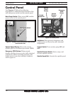
OPERATION
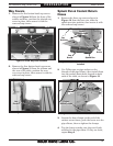
Table Movement
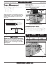
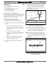
The mill table moves in three directions, as
illustrated in Figure 19:
• X-axis (longitudinal)
• Y-axis(cross)
• Z-axis(vertical)
These movements are controlled by table ball
handles and the Z-axis crank. Additionally, the
table can be moved along the X-axis with the
power feed.
Figure 19. The directions of table movement.
X-Axis or Longitudinal Travel
(Left & Right)
Y-Axis or
Cross Travel
(In & Out)
Z-Axis or Vertical Elevation
(Up & Down)
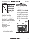
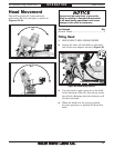
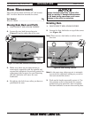
Graduated Index Rings
The table ball handles and elevation crank have
graduated index rings attached (see Figure 21)
that are used to accurately determine table
movement in the increments listed in the table
below:
Axis Individual
Increment
One Full
Revolution
X 0.001" 0.200"
Y 0.001" 0.200"
Z 0.001" 0.100"
Figure 21. Graduated table index rings.
Index Rings
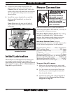
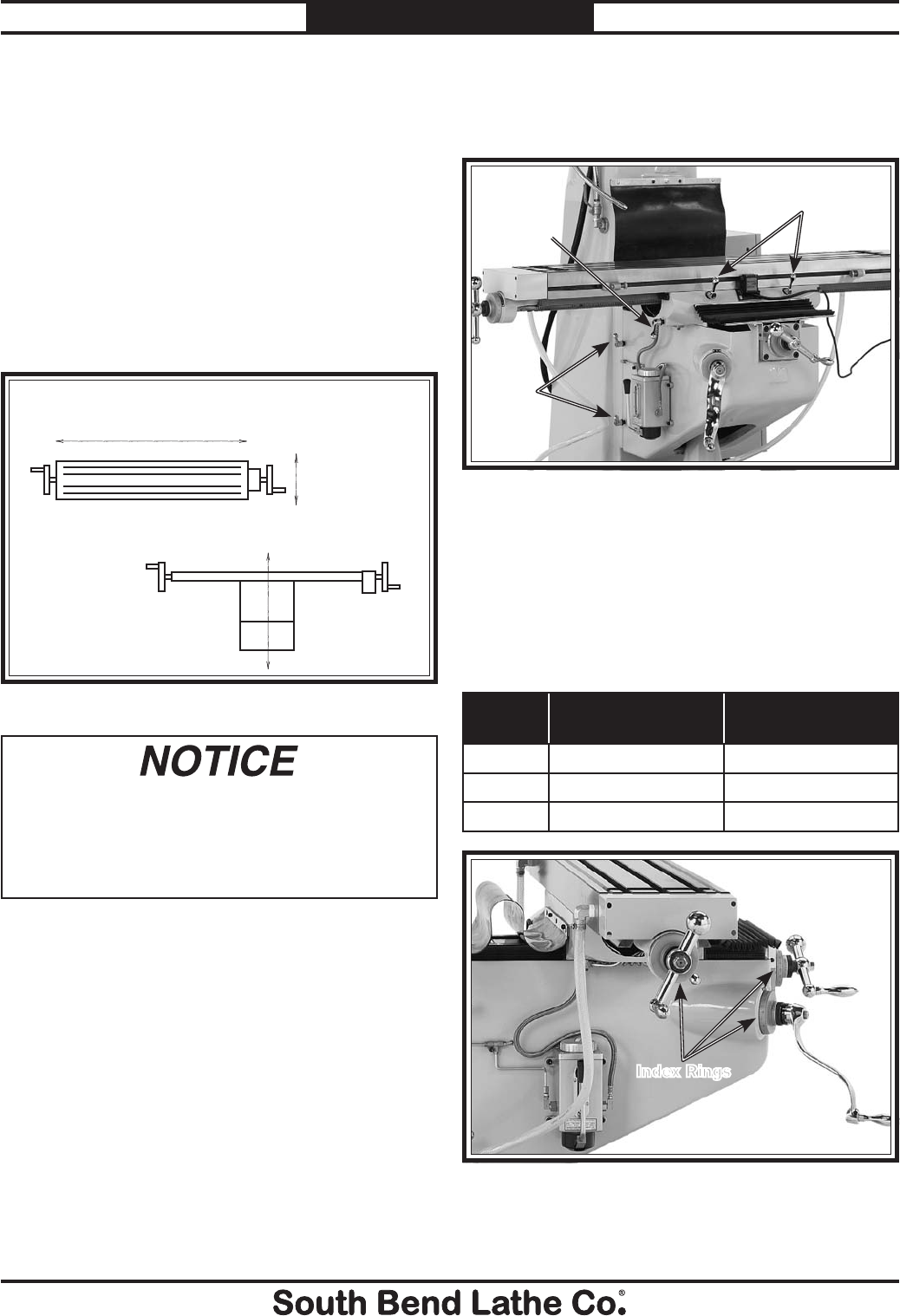
Table Locks
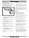
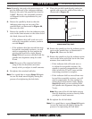
Refer to Figure 20 for the locations of the locks
used to secure the table in place.
Figure 20. Locations of table locks.
X-Axis Locks
Z-Axis
Locks
Y-Axis
Lock
Always keep the table locked in place unless
table movement is required for your operation.
Unexpected movement of the table during
operations could cause damage to the cutter
or workpiece.