


-20-
For Machines Mfg. Since 8/09
Model SB1027
PREPARATION
5. Loosen the hose clamp screws above the
coolant return screens in the base (see
Figure 13 on the previous page), insert the
hoses so that they will drain into the screens,
then re-tighten the clamp screws to secure
them in place.
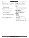
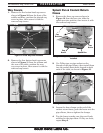
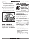
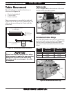
6. Install the coarse downfeed lever and the
fine downfeed handwheel, as shown in
Figure 14.
Note: Make sure the pins on the back of
these devices are fully seated in the hubs
before use.
The machine was lubricated at the factory, but
we strongly recommend that you inspect all
lubrication points yourself and provide additional
lubrication if necessary. Refer to Lubrication on
Page 43 for specific details.
Initial Lubrication
Power Connection
Electrocution or fire
may occur if machine is
ungrounded, incorrectly
connected to power, or
connected to an undersized
circuit. Use a qualified
electrician to ensure a safe
power connection.
Once the machine is set up and assembled as
previously described in this manual, it is ready to
be connected to the power source.
Note About Required Power Source: The milling
machine is equipped with a Yaskawa phase
inverter that changes single-phase power into
3-phase which is used by the spindle motor.
Note About Extension Cords: Using an
incorrectly sized extension cord may decrease the
life of electrical components on the machine.
Required Power Source ...........220V, Single-Phase
Full Load Amp Draw ............................ 8.95 Amps
Required Voltage Range ................................ 220V
Frequency ...................................................... 60 Hz
Minimum Circuit Size ............................. 15 Amps
Recommended Power Cord ...14 AWG/3C/300VAC
Recommended Plug/Receptacle .......... NEMA 6-15
Minimum Extension Cord Size ................14 AWG
Maximum Extension Cord Length ................ 50 ft.
To connect the mill to power:
1. Make sure the incoming power source and
the power cord meet the requirements above.
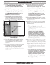
2. Use the correct size strain relief when you
feed the power cord through the bottom of
the electrical cabinet.
3. Connect the power cord to the terminals as
illustrated in the Electrical Box Wiring
Diagram on Page 58.
Figure 14. Coarse downfeed lever and fine downfeed
handwheel installed.
Coarse
Downfeed
Lever
Fine
Downfeed
Handwheel