


-30-
For Machines Mfg. Since 8/09
Model SB1027
OPERATION
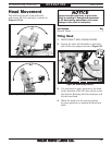
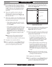
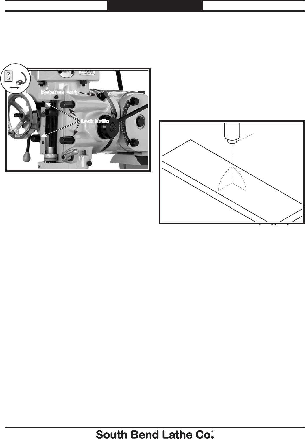
Rotating Head
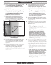
1. DISCONNECT MILL FROM POWER!
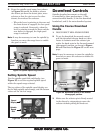
2. Loosen the four rotation lock bolts on the
face of the head shown in Figure 26.
3. Use one hand to apply pressure to the head
in the direction of rotation, then slowly turn
the rotation bolt.
4. Re-tighten the lock bolts when you have the
head in the desired position.
Figure 26. Head rotating controls.
Lock Bolts
Rotation Bolt
!
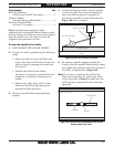
Tramming Spindle
After positioning the head at an angle and when
your operation requires that the spindle axis be
precisely perpendicular to the table, you must
tram or align the spindle with the table to ensure
the spindle is exactly 90° to the table.
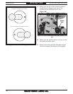
This procedure involves mounting a dial test
indicator to the quill or spindle, rotating it
around the table, and adjusting the spindle
axis (Z-axis) 90° to the table X- and Y-axes, as
illustrated in Figure 27.
We encourage you to research the many
variations of spindle tramming to find the one
that works best for you. If you do not already
have a preference for performing this operation,
use the following widely-used procedure for
accurately tramming the spindle to the table.
Keep in mind that all workpiece top surfaces are
not exactly parallel with the table top. You may
choose to tram the spindle to the top surface of
the workpiece after it is mounted instead of that
of the table.
Figure 27. Spindle axis perpendicular to the table X-
and Y-axes.
Table
Spindle
X-Axis
Y-Axis
Z-Axis
90º
90º